
In machining, in order to maximize the processing quality and repeat accuracy, it is necessary to correctly select and determine the appropriate tool. For some challenging and difficult machining, the choice of tool is particularly important.
1. High-speed tool path
1. High-speed tool path
The CAD / CAM system achieves extremely high cutting accuracy by precisely controlling the arc length of the cutting tool in the high-speed cycloid tool path. When the milling cutter cuts into the corner or into other complex geometric shapes, the amount of knife eating will not increase. To take full advantage of this technological advancement, tool manufacturers have designed and developed advanced small-diameter milling cutters. Small-diameter milling cutters can cut more workpiece materials in a unit time by using high-speed tool paths, and obtain a higher metal removal rate.
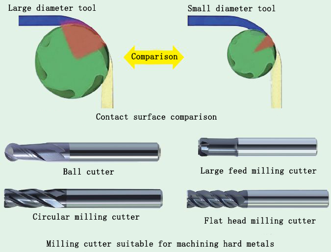
During machining, too much contact between the tool and the surface of the workpiece can easily cause the tool to fail quickly. An effective rule of thumb is to use a milling cutter with a diameter of about 1/2 of the narrowest part of the workpiece. When the radius of the milling cutter is smaller than the size of the narrowest part of the workpiece, there is room for the tool to move left and right, and the smallest angle of eating can be obtained. Milling cutters can use more cutting edges and higher feed rates. In addition, when a milling cutter with a diameter of 1/2 of the narrowest part of the workpiece is used, the cutting angle can be kept small without increasing the turning of the cutter.
Machine stiffness also helps determine the size of the tools that can be used. For example, when cutting on a 40-taper machine, the diameter of the milling cutter should normally be <12.7mm. The use of a cutter with a larger diameter will produce a larger cutting force that may exceed the machine's ability to bear, resulting in chatter, deformation, poor surface finish, and shortened tool life.
When using the newer high-speed tool path, the sound of the milling cutter at the corner is the same as that of straight line cutting. The sound produced by the milling cutter during the cutting process is the same, indicating that it has not been subjected to large thermal and mechanical shocks. The milling cutter makes a screaming sound every time it turns or cuts into the corner, which indicates that the diameter of the milling cutter may need to be reduced to reduce the angle of eating. The sound of cutting remains unchanged, indicating that the cutting pressure on the milling cutter is uniform and does not fluctuate up and down with the change of the geometry of the workpiece. This is because the angle of the knife is always constant.
2. Milling small parts
The large feed milling cutter is suitable for the milling of small parts, which can produce a chip thinning effect, making it possible to mill at a higher feed rate.
In the processing of spiral milling holes and milling ribs, the tool will inevitably make more contact with the machining surface, and the use of a large feed milling cutter can minimize the surface contact with the workpiece, thereby reducing cutting heat and tool deformation .
In these two kinds of processing, the large feed milling cutter is usually in a semi-closed state during cutting. Therefore, the maximum radial cutting step should be 25% of the diameter of the milling cutter, and the maximum Z cutting depth of each cutting should be It is 2% of the diameter of the milling cutter. cnc machining part
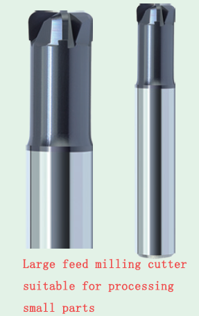
In the spiral milling hole, when the milling cutter cuts into the workpiece with the spiral cutter rail, the spiral cutting angle is 2 ° ~ 3 ° until it reaches the Z-cut depth of 2% of the diameter of the milling cutter.
If the large-feed milling cutter is in an open state during cutting, its radial walking step depends on the hardness of the workpiece material. When milling workpiece materials with hardness HRC30-50, the maximum radial cutting step should be 5% of the milling cutter diameter; when the material hardness is higher than HRC50, the maximum radial cutting step and the maximum Z per pass The cutting depth is 2% of the diameter of the milling cutter. aluminum part
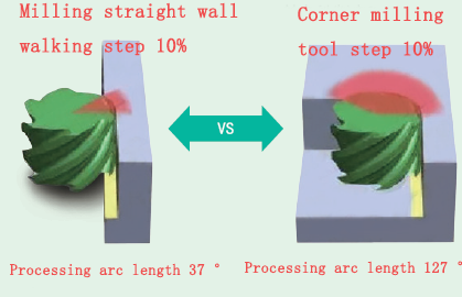
3. Milling straight walls
When milling with flat ribs or straight walls, it is best to use an arc cutter. Arc cutters with 4 to 6 edges are particularly suitable for profile milling of straight or very open parts. The more the number of blades of the milling cutter, the greater the feed rate that can be used. However, the machining programmer still needs to minimize the contact between the tool and the surface of the workpiece and use a smaller radial cutting width. When machining on a machine tool with poor rigidity, it is advantageous to use a milling cutter with a smaller diameter, which can reduce contact with the surface of the workpiece. cnc milling part
The cutting step and cutting depth of the multi-edge arc milling cutter are the same as those of the high-feed milling cutter. The cycloid tool path can be used to groove the hardened material. Make sure that the diameter of the milling cutter is about 50% of the width of the groove, so that the milling cutter has enough space to move, and ensure that the angle of the cutter will not increase and generate excessive cutting heat.
The best tool for a particular machining depends not only on the material being cut, but also on the type of cutting and milling method used. By optimizing tools, cutting speeds, feed rates and machining programming skills, parts can be produced faster and better at lower machining costs.
Anebon Metal Products Limited can provide CNC machining, die casting, sheet metal machining services, please feel free to contact us.
Tel: +86-769-89802722 Email: info@anebon.com Website : www.anebon.com
Post time: Apr-28-2020