
How much do you know about the classification of CNC machine tools?
Classification of CNC machine tools is based on the function, structure and application.
We will now look at different classifications:
Based on Function
Turning machines: These machines perform mainly turning operations on cylindrical or conical components.
These machines can be used to mill flat or complex surfaces.
Based on Structure
Horizontal Machining Centers: The spindle and workpiece are placed horizontally on a table.
Vertical Machining Centers: The spindle and workpiece are placed vertically on a table.
Multi-axis machines: These machines are equipped with multiple axes (3 or more), allowing them to perform precise and complex operations.
Based on the Application
Drilling Machines are machines that perform primarily drilling operations.
Grinding machines: These machines can be used to grind and polish metal.
Laser Cutting Machines: Laser technology is used to cut various materials.
Electro-Discharge Machines (EDM): These machines shape and drill electrically conductive material.
The classification methods for CNC machines are different. There are many types and specifications. It can be classified using the classification methods above, as well as the four principles of function and structure.
1. Classification of machine tools according to their control trajectory
1) Point control CNC machines
The only requirement for point control is the precise positioning of moving parts from one machine tool to another. The requirements of the trajectory between points for motion are not very strict. During the movement, no processing is done. It is not important how the movement occurs between each coordinate axis. To achieve accurate and fast positioning, it is important to first move the distance between two points quickly, then slowly approach the position point to ensure accuracy. The motion trajectory is shown below.
CNC milling machines and CNC punching machines are examples of machine tools that have point control capabilities. CNC systems that are used solely for point control have become rare due to the advancement of CNC technology.
(2) Linear control CNC machine tools
Parallel control CNC machines are also known as linear control CNC machines. It has the characteristic that it controls not only the precise positioning between points but also the speed of movement and the route (trajectory), between two points. Its movement is related only to the machine tool coordinates axes moving in parallel. This means that only one coordinate is controlled at a time. The tool can be used to cut at the feed rate specified during the shifting process. It can generally only be used to process rectangular and stepped components.
CNC lathes with linear control are mainly CNC milling machines and CNC grinders. This machine tool’s CNC system is also known as a linear-control CNC system. In the same way, CNC machines that are used exclusively for linear control is rare.
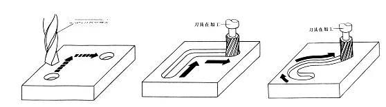
(3) 3D contour control CNC machine tools
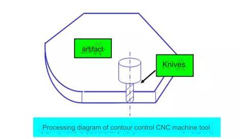
Continuous control CNC machines are also known as contour control CNC machines. The control feature of this machine is the ability to control two or more motion coordinates at once.
To ensure that the relative motion of the tool on the workpiece contour is in accordance with the machining contour of the workpiece, it is necessary to accurately coordinate the displacement and speed of each coordinated motion according to the proportional relationship prescribed.
In order to use this control method, a CNC device must have the interpolation function. Interpolation describes the shape of a straight line or an arc by mathematical processing performed by the interpolation operators in the CNC system. This is based on basic data inputted by the program, such as the coordinates for the end points of a straight line, coordinates for the end points of an arc, or the radius or center coordinate. While calculating, assign pulses to each controller of the coordinate axis according to the results. This controls the linkage displacement for each coordinate to conform to the desired contour. During movement, the tool cuts continuously the surface of the workpiece, which allows for various processing such as straight lines, curves, and arcs. Contour-controlled machining trajectory.
These machine tools include CNC lathes and milling machines as well as CNC wire-cutting machines, machining centres, etc. The CNC devices that correspond to them are called contour control systems. It can be classified into three types based on the number of axes that it controls: form
1 Two-axis links: used mainly for CNC lathes that process rotating surfaces, or CNC milling machines that process cylindrical surfaces curved.
2 Semi-linkage 2 axes: This is used mainly for controlling machine tools that have more than 3 axes. Two axes may be linked and the third axis may perform periodic feeding.
3 Three-axis Linkage: This is a linkage that involves three linear coordinate axes, usually X/Y/Z, and is used by CNC milling machines, machine centers, etc. The second type allows you to control two linear coordinates simultaneously in X/Y/Z, as well as the rotation coordinate axis which rotates around the linear coordinate axes.
In a turning machine center, for example, the linkage between two linear coordinate axes (X-axis and Z-axis in longitudinal direction) must be controlled simultaneously with the linkage to the spindle’s (C-axis), which rotates around the Z axis.
4 Four-axis Linkage: Control the three linear coordinates X, Y and Z simultaneously to be linked with one rotational coordinate axis.
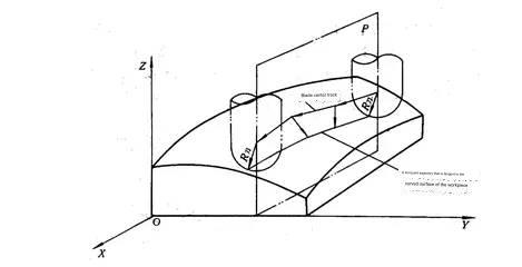
5 Five-axis Linkage: This allows you to control the linking of three coordinate axes at once, X/Y/Z. The tool also controls simultaneously two of the A B and C coordinates axes which rotate around these linear axes. This gives a total of five axes. The tool can now be positioned anywhere in space.
The tool can be controlled to rotate around both the x and y axes simultaneously, so it always cuts in the same direction as the contour surface. This ensures the smoothness and accuracy of the surface. The machined surface is smoother, increasing efficiency.
2. Classification of servo-controlled systems
1) Open-loop CNC machine tools
This type of machine tool has an open-loop feed servo, which means that there is no feedback detection device. Its drive motor is usually a stepper. A stepper motor’s main feature is that it rotates a full step every time the control system changes the pulse signal. The motor has a self-locking feature and can be used to adjust the distance angle.
The pulse distributor controls the drive circuit by using the feed command signal from the CNC system. The number of pulses and pulse frequency can be changed to control the coordinate displacement, the displacement speed, or the displacement. direction.
The main features of this method are its simplicity, ease of use, and low cost. There is no instability problem with the control system because the CNC system only sends one-way signals. The accuracy of the displacement is low, however, because the mechanical transmission error is not corrected through feedback.
This control method was used by all early CNC machines, but it had a high failure rate. Despite the improvements in the drive circuits, this control method is still used widely today. This control method, especially in our country is used for general CNC systems that are economical and to transform old equipment using CNC. This control method also allows a single chip computer or single board computer to be configured as a CNC machine, which reduces the cost of the system.
Machine tools with closed-loop control
This type of CNC machine tool uses closed-loop control. The motor drive can be either DC or AC and must have both position feedback and velocity feedback configured to detect any actual movement of the moving part at any point during the processing. The CNC system feeds the amount back in real time to the comparator. The command signal is obtained through interpolation and compared to the amount. The difference is then used to control the servodrive, which drives the displacement component in order to eliminate the error.
Depending on the location and feedback device of the position feedback detector, there are two modes: closed loop (full) and semi-closed loop (semi-closed loop).
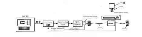
1 Closed loop control
The position feedback device, as shown in the figure uses a linear distance detection element. (At present, a grating rule is used most commonly) This is mounted on the saddle of a machine tool. It detects directly the linear displacement in the machine tool coordinates. The signal from the motor can be eliminated through feedback. Transmission error is reduced in the mechanical transmission chain, which results in high accuracy for static positioning of the machine.
The dynamic response of the mechanical transmission chain as a whole is much longer than the electrical response. The entire closed-loop control system is very difficult to stabilize, and its design and adjustments are quite complex. This closed-loop method of control is used primarily for CNC coordinate machines, CNC precision grinding machines, etc. That require high precision.
2 Semi-closed loop control
The position feedback is based on angle detection components, which are currently mainly encoders. The servo motors or screws are fitted with angle detection components (currently mainly encoders). The control characteristics of the system are more stable because the majority of mechanical transmission links is not in the closed-loop. Software fixed value compensation can improve accuracy of mechanical transmission errors, such as screw error. Most CNC machines use semi-closed loop mode.
3 Dimensional hybrid control CNC machines
To create a hybrid control system, the characteristics of each control method can be concentrated selectively. In order to meet the requirements of certain machine tools and compensate for the differences between the two methods, it is recommended that a hybrid control scheme be used. Two common methods are open-loop compensating type and semi-closed loop compensating type.
3. CNC Systems classified according to their functional level
The CNC systems are classified into three categories based on their functional level: low, medium, and high. This method of classification is widely used in our country. The classification standards are different from one period to the next. According to the current development level, different types of CNC systems are divided into three categories based on certain functions and indicators. Medium and high-end CNC systems are often referred to as full-function or standard CNC.
(1) Metal Cutting
It refers to CNC machines that perform various cutting operations such as cnc turning & milling. This can be divided into two main categories.
CNC machines such as lathes and milling machines.
The main feature of a machining centre is its tool library, which has an automatic tool-changing mechanism. It only passes the workpiece through the machine once. After clamping the workpiece, the cutting tools are replaced automatically. Various processes, including milling (turning), keys, reaming (drilling), and thread taping are performed continuously on each surface of the piece on the same machine, for example, (building/milling). Center, turning center, drilling center, etc.
(2) Metal Forming
Refers to CNC machines that are used for extrusion, punching and pressing, as well as drawing, and other forming operations. Some of the most commonly used CNC machines include CNC presses and CNC pipe benders.
(3) Special Processing Category
CNC wire EDM machines are the most common, followed by cnc metal cutting machines and CNC laser processing machines.
(4) Measuring and drawing
Included in this category are mainly three-dimensional coordinate measuring instruments, CNC tool setters, CNC plotters, etc.
Anebon’s primary objective will be to offer you our shoppers a serious and responsible enterprise relationship, supplying personalized attention to all of them for New Fashion Design forOEM Shenzhen Precision Hardware Factory Custom Fabrication CNC milling process, precision casting, prototyping service. You may uncover the lowest price here. Also you are going to get good quality products and solutions and fantastic service here! You should not be reluctant to get hold of Anebon!
New Fashion Design for China CNC Machining Service and Custom CNC Machining Service, Anebon has numbers of foreign trade platforms, which are Alibaba,Globalsources,Global Market,Made-in-china. “XinGuangYang” HID brand products and solutions sell very well in Europe, America, Middle East and other regions more than 30 countries.
Post time: Oct-06-2023