
Shaft components such as crankshafts, camshafts, and cylinder liners for engines use chucks in each process of processing. During processing, the chucks have the functions of centering, clamping and driving the workpiece. According to the ability of the chuck to hold the workpiece and maintain the center, it is divided into rigid chuck and floating chuck. This article mainly discusses the selection principles and daily maintenance points of these two chucks. 5aixs cnc machining parts
Rigid chucks and floating chucks are very different in structure and adjustment method. Taking a series of chucks of a Japanese brand as an example, Figure 1 shows the action process of the floating chuck: the workpiece is under the action of the positioning support block and the top. Axial and radial positioning and clamping are carried out, and then the chuck cylinder drives the chuck center tie rod, gap adjustment plate, jaw arm support plate, spherical joint and jaw arm through the tie rod, and finally realizes the chuck jaw to clamp the workpiece. .
When there is a large deviation of the coaxiality between the center of the three jaws of the chuck and the center of the workpiece, the jaw of the chuck that contacts the workpiece first will be subjected to a force F2, which is transmitted to the jaw arm support plate through the jaw arm and the spherical joint. F3 acts on the claw arm support plate. For the floating chuck, there is a gap between the central pull rod of the chuck and the claw arm support plate. Under the action of the force F3, the claw arm support plate uses the floating gap (gap adjustment plate, The central pull rod of the chuck and the support plate of the jaw arm together form the floating mechanism of the chuck), which will move in the direction of the force until the three jaws completely clamp the workpiece.
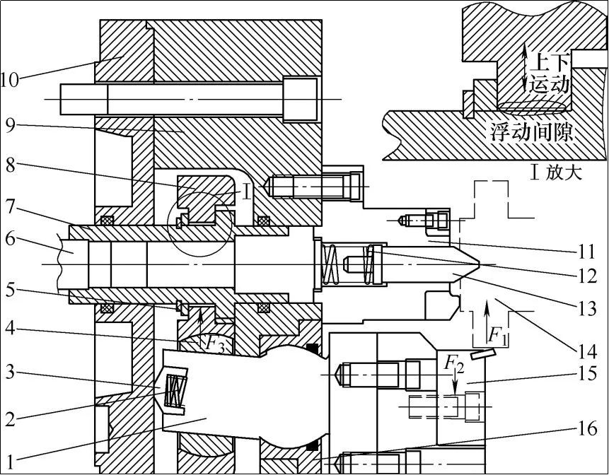
Figure 1 Floating chuck structure
1. Claw arm 2. 12. Rectangular spring 3. Spherical top cover 4. Spherical joint
5. Clearance adjustment plate 6. Cylinder pull rod 7. Chuck center pull rod
8. Claw arm support plate 9. Chuck body 10. Chuck rear end cover
11. Positioning support block 13. Top 14. Workpiece to be processed
15. Chuck jaws 16. Ball support
Figure 2 shows the action process of the rigid chuck: under the action of the positioning support block and the top, the workpiece is positioned and clamped axially and radially, and then the chuck oil cylinder drives the central pull rod, spherical joint and jaw of the chuck through the pull rod. The arm moves, and finally the chuck jaws clamp the workpiece. Since the center pull rod of the chuck is rigidly connected with the spherical joint and the jaw arm, after the chuck jaws (three jaws) are clamped, a clamping center will be formed. The clamping center formed by the top does not overlap, and the workpiece will have obvious clamping deformation after the chuck is clamped. Before the chuck is used, it is necessary to adjust the overlap between the center of the chuck and the center of the center to ensure that the chuck will not appear virtual after clamping. Clamped condition.
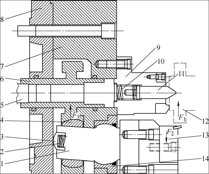
Figure 2 Rigid chuck structure
1. Claw arm
2. 10. Rectangular spring
3. Spherical top cover
4. Spherical joint
5. Cylinder tie rod
6. Chuck center tie rod
7. Chuck body
8. Chuck rear end cover
9. Positioning support block
10. Top
11. Workpiece to be processed
12. Chuck jaws
13. Spherical support
From the analysis of the mechanism of the chuck in Figure 1 and Figure 2, the floating chuck and the rigid chuck have the following differences.
Floating chuck: As shown in Figure 3, in the process of clamping the workpiece, due to the different heights of the workpiece blank surface or the large roundness tolerance of the blank, the No. 3 jaw will come into contact with the workpiece surface and the No. 1 and No. 2 jaws will appear. If the workpiece has not been touched yet, at this time, the floating mechanism of the floating chuck works, using the surface of the workpiece as the support to float the No. 3 jaw. As long as the floating amount is sufficient, the No. 1 and No. 2 jaws will eventually be clamped. The workpiece has little effect on the center of the workpiece.
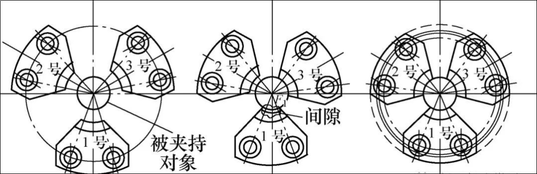
Figure 3 Clamping process of floating chuck jaws
Rigid chuck: As shown in Figure 4, during the clamping process, if the concentricity between the chuck and the workpiece is not adjusted properly, the No. 3 jaw will contact the workpiece, and the No. 1 and No. 2 jaws will not be in contact with the workpiece. , then the chuck clamping force F1 will act on the workpiece. If the force is large enough, the workpiece will be offset from the predetermined center, forcing the workpiece to move to the center of the chuck; when the clamping force of the chuck is small, some cases will occur. When the jaws cannot fully contact the workpiece, vibration occurs during machining. cnc milling connector
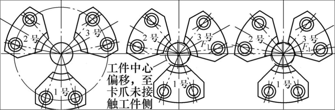
Figure 4 Clamping process of rigid chuck jaws
Adjustment requirements before the chuck is used: The rigid chuck will form the clamping center of the chuck itself after clamping. When using the rigid chuck, it is necessary to adjust the clamping center of the chuck to coincide with the clamping and positioning center of the workpiece, as shown in the figure 5 shown. cnc machining aluminum part
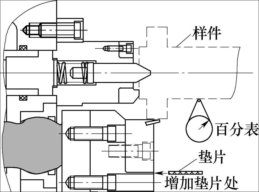
Figure 5 Adjustment of the rigid chuck center
According to the above structural analysis, it is recommended to follow the following principles in the adjustment and maintenance of the chuck: The lubrication and grease of the movable parts inside the chuck are regularly replaced. The movement between the moving parts inside the chuck is basically sliding friction. It is necessary to add and regularly replace the specified grade of lubricating oil/grease according to the maintenance requirements of the chuck. When adding grease, it is necessary to squeeze out all the grease used in the previous period, and then block the oil discharge port after clamping the chuck to prevent the internal cavity of the chuck from being held back.
Regular inspection and adjustment of the clamping center of the rigid chuck and the center of the workpiece: The rigid chuck needs to periodically measure whether the center of the chuck and the center of the workpiece spindle are consistent. Measure the runout of the disc. If it exceeds the required range, add spacers appropriately at one or two jaws corresponding to the high point, and repeat the above steps until the requirements are met.
Periodic inspection of the floating amount of the floating chuck (see Figure 6). In daily chuck maintenance, it is necessary to regularly measure the floating amount and floating precision of the floating chuck, and provide guidance for the internal maintenance of the chuck in the later stage. The measurement method of floating precision: after the chuck clamps the sample, put the chuck to be measured. Rotate the claw to a convenient measurement position, measure the dial indicator (need to attach the magnetic meter base to the moving shaft), and mark the measurement point as the zero point position. Then control the servo axis to move the dial indicator, open the chuck, place a gasket with a thickness of Amm between the jaws to be measured and the sample, clamp the sample on the chuck, move the dial indicator to the zero point position, and confirm whether the data pressed by the dial indicator is about Amm. If it is, it means that the floating accuracy is good. If the data differs greatly, it means that there is a problem with the floating mechanism of the chuck. The measurement of other jaws is the same as above.
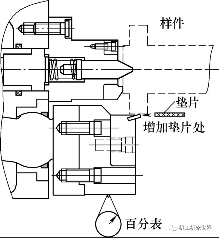
Figure 6 Inspection of the floating amount of the floating chuck
Regular replacement of parts such as seals, gaskets and springs inside the chuck: rectangular springs, chuck body, chuck rear end cover, rectangular springs and seals and springs in spherical supports need to be carried out according to the frequency of use and the above test results. Replace regularly, otherwise it will be damaged due to fatigue, resulting in floating amount and rigid chuck runout.
Through the above analysis of the key points of chuck structure adjustment and maintenance, pay attention to the following principles in the selection of chucks: if the chuck clamping part of the processed part is the blank surface, the floating chuck is preferred, and the rigid chuck is used in the workpiece. The chuck clamping surface of the machined part is the surface after roughing, semi-finishing/finishing. After following the above basic rules, it is necessary to make precise selections according to different working conditions.
Selection of rigid chuck: ①The machining conditions require a large amount of cutting and a large cutting force. After being clamped by the workpiece to be processed and supported by the center frame, a strong workpiece rigidity and a large workpiece rotational driving force are required. ②When there is no one-time centering mechanism such as the top, and the design of the chuck centering is required.
Floating chuck selection: ①High requirements for the centering of the workpiece spindle. After the chuck is clamped, its own floating will not disturb the primary centering of the workpiece spindle. ②The cutting amount is not large, and it is only necessary to drive the workpiece spindle to rotate and increase the rigidity of the workpiece.
The above explains the structural differences, maintenance and selection requirements of floating and rigid chucks, which are helpful for the use and maintenance of chucks. If you need a deeper understanding and flexible use, you need to constantly summarize experience in on-site use and maintenance.
Anebon Metal Products Limited can provide CNC Machining、Die Casting、Sheet Metal Fabrication service, please feel free to contact us.
Tel: +86-769-89802722 E-mail: info@anebon.com URL: www.anebon.com
Post time: Mar-31-2022