
The development of tooling fixtures usually takes place in accordance with the particular needs of a given process, once the parts’ machining process has been established. It is important to fully consider the feasibility of implementing the fixtures while formulating the process. When creating the tooling fixtures, adjustments to the process should be suggested when necessary.
The quality of the tooling fixture design should be evaluated based on its ability to consistently ensure the processing quality of the workpiece, achieve high production efficiency, minimize costs, enable convenient chip removal, ensure safe operation, save on labor, and facilitate easy manufacturing and maintenance. Parameters for assessment include these factors.
1. Fundamental guidelines for designing tooling fixtures
1)Ensure the stability and dependability of workpiece positioning during utilization;
2)Provide adequate load-bearing or clamping strength to guarantee workpiece processing on the fixture;
3)Enable simple and rapid operation during the clamping process;
4)Incorporate wearable parts with a replaceable structure, ideally avoiding the use of other tools when conditions allow;
5)Establish reliability in the repeated positioning of the fixture during adjustment or replacement;
6)Minimize complexity and costs by avoiding intricate structures whenever feasible;
7)Utilize standard parts as component parts to the greatest extent possible;
8)Establish internal product systematization and standardization within the company.
2. Basic knowledge of tooling and fixture design
An excellent machine tool fixture must meet the following basic requirements:
1)Guaranteeing workpiece machining precision necessitates selecting the appropriate positioning datum, technique, and components, and conducting positioning error analysis if required. Attention should also be paid to the influence of the fixture’s structural elements on processing to ensure that the fixture meets the workpiece’s accuracy specifications.
2)To enhance production efficiency, tailor the complexity of special fixtures to match the production capacity. Utilize various fast and efficient clamping mechanisms whenever possible to simplify operations, decrease auxiliary time, and boost production efficiency.
3)Opt for simple and rational structures for special fixtures with excellent operational performance to streamline manufacturing, assembly, adjustment, inspection, and maintenance processes.
4)High-performing work fixtures should possess ample strength and rigidity, coupled with easy, efficient, safe, and reliable operation. Whenever feasible and cost-effective, employ pneumatic, hydraulic, and other mechanized clamping devices to reduce operator labor intensity. Additionally, the tooling fixture should facilitate chip removal and implement structures, if necessary, to prevent chips from compromising workpiece positioning, tool damage, or causing heat accumulation and process system deformation.
5)Economically efficient special fixtures should utilize standard components and structures as much as possible. Strive for simple designs and easy manufacturing to minimize fixture production costs. Consequently, perform the necessary technical and economic analyses of the fixture solution during the design phase based on order and production capacities to enhance the fixture’s economic benefits during production.
3. Overview of standardization of tooling and fixture design
1. Basic methods and steps of tooling and fixture design
Preparation before design The original data for tooling and fixture design include the following:
a) Provide design notices, completed part drawings, preliminary sketches, and process routes, alongside other technical details. Gain an understanding of the technical requirements for each process, including positioning and clamping methods, processing details from the preceding stage, surface conditions, machine tools employed, tooling, inspection equipment, machining tolerances, and cutting quantities.
b) Comprehend the production batch size and fixture requirements.
c) Familiarize yourself with the primary technical parameters, performance, specifications, accuracy, and dimensions associated with the structure of the fixture connecting part of the machine tool used.
d) Maintain a standard inventory of fixture materials.
2. Issues to consider in the design of tooling fixtures
The clamp design generally has a single structure, which gives the impression that the structure is not very complicated. Especially now the popularity of hydraulic clamps has greatly simplified the original mechanical structure. However, if detailed considerations are not taken during the design process, unnecessary troubles will inevitably occur:
a) When designing, ensure that the blank margin of the workpiece is accurately considered to prevent interference due to oversizing. Prepare the blank drawing before proceeding with the design process to allow for ample space.
b) To ensure efficient operation and smooth chip removal of the fixture, it is crucial to address potential issues such as iron filings accumulation and poor cutting fluid outflow early in the design stage. Anticipating and resolving processing problems from the outset is essential to optimize the purpose of fixtures in improving efficiency and ease of operation.
c) Emphasize the overall openness of the fixture to simplify the installation process for operators, avoiding time-consuming and labor-intensive tasks. Neglecting fixture openness is unfavorable in design.
d) Always adhere to basic theoretical principles in fixture design to maintain accuracy and longevity. Designs should not compromise these principles, even if they appear to meet initial user requirements, as a good design should withstand the test of time.
e) Consider the quick and easy replacement of positioning components to address severe wear and avoid designing larger, more complex parts. Ease of replacement should be a key factor in component design.
The accumulation of fixture design experience is very important. Sometimes design is one thing and practical application is another, so good design is a process of continuous accumulation and summary.
Commonly used work fixtures are mainly divided into the following categories according to their functionality:
01 clamp mold
02 Drilling and milling tooling
03 CNC, instrument chuck
04 Gas testing and water testing tooling
05 Trimming and punching tooling
06 Welding tooling
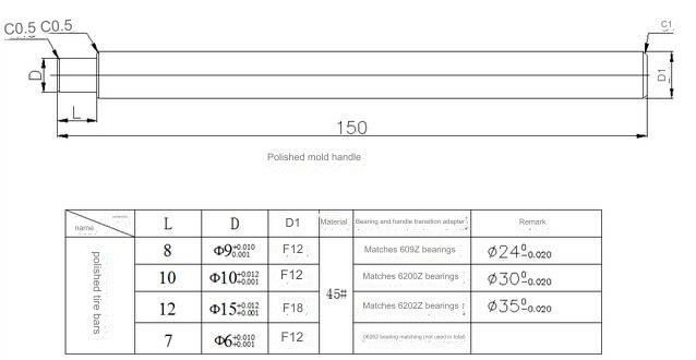
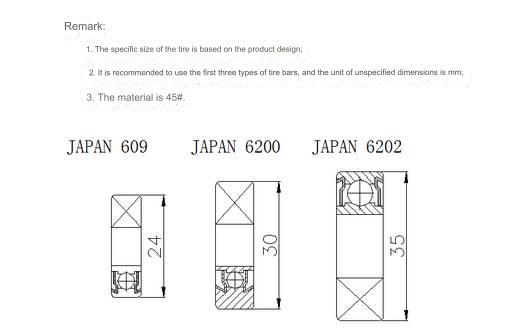
07 Polishing jig
08 Assembly tooling
09 Pad printing, laser engraving tooling
01 clamp mold
Definition: A tool for positioning and clamping based on product shape
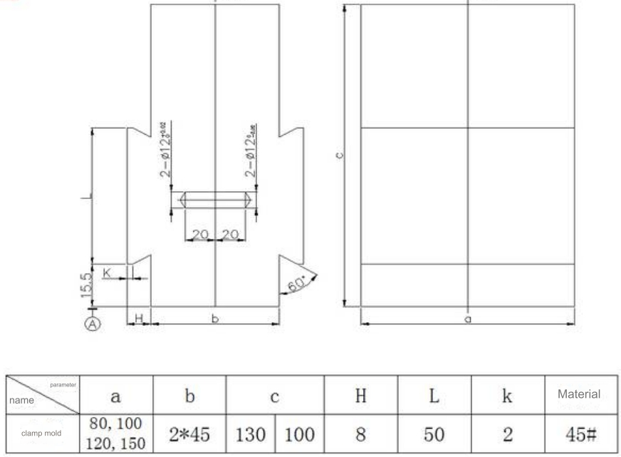
Design Points:
1)This kind of clamp finds its primary application in vise, and it offers the flexibility to be trimmed as per the requirements.
2)Additional positioning aids can be integrated into the clamping mold, typically secured through welding.
3)The diagram above is a simplified representation, and the dimensions of the mold cavity structure are contingent on the specific circumstances.
4)Properly position the 12mm diameter locating pin onto the movable mold, while the corresponding hole on the fixed mold is designed to smoothly accommodate the pin.
5)During the design phase, the assembly cavity should be adjusted and enlarged by 0.1mm, taking into consideration the outline surface of the non-shrunken blank drawing.
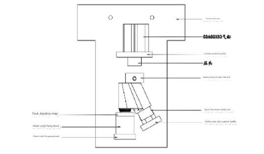
02 Drilling and milling tooling
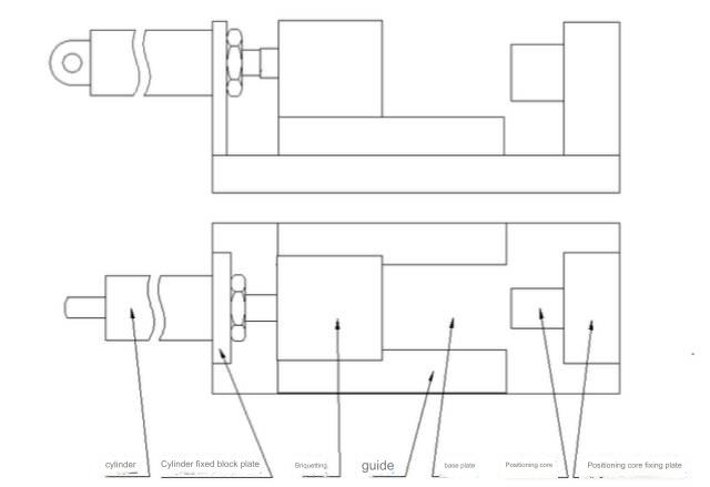
Design Points:
1)If required, additional positioning mechanisms can be incorporated into the fixed core and its corresponding fixed plate.
2)The depicted image is a basic structural outline. Actual conditions necessitate tailored design in line with the product’s structure.
3)The choice of cylinder is influenced by the product’s dimensions and the stress it undergoes during processing. SDA50X50 is the prevailing choice in such scenarios.
03 CNC, instrument chuck
A CNC chuck
Toe-in chuck
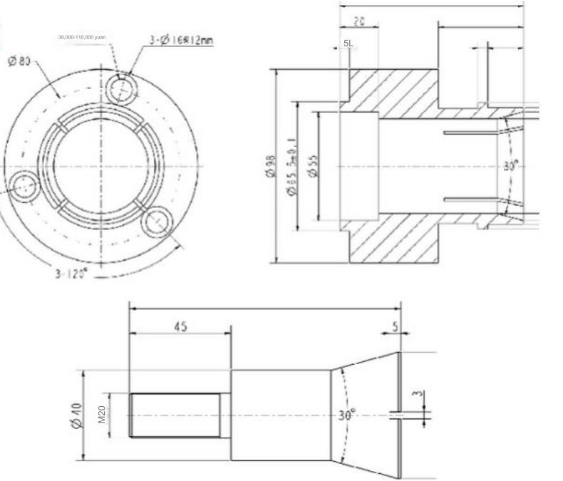
Design Points:
1. The dimensions not marked in the above picture are based on the inner hole size structure of the actual product;
2. The outer circle that is in positioning contact with the inner hole of the product needs to leave a margin of 0.5mm on one side during production, and is finally installed on the CNC machine tool and then finely turned to size to prevent deformation and eccentricity caused by the quenching process;
3. It is recommended to use spring steel as the material for the assembly part and 45# for the tie rod part;
4. The thread M20 on the tie rod part is a commonly used thread, which can be adjusted according to the actual situation.
Instrument toe-in chuck
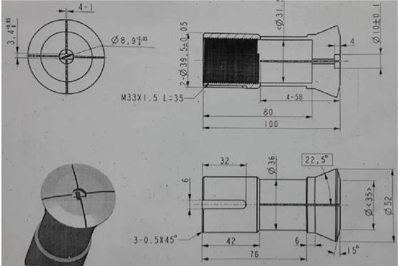
Design Points:
1. The above picture is a reference diagram, and the assembly dimensions and structure are based on the actual product’s dimensions and structure;
2. The material is 45# and quenched.
Instrument external clamp
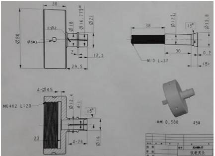
Design Points:
1. The above picture is a reference diagram, and the actual size depends on the inner hole size structure of the product;
2. The outer circle that is in positioning contact with the inner hole of the product needs to leave a margin of 0.5mm on one side during production, and is finally installed on the instrument lathe and then finely turned to size to prevent deformation and eccentricity caused by the quenching process;
3. The material is 45# and quenched.
04 Gas testing tooling
Design Points:
1) The image provided serves as a guide for gas testing tooling. The design of the specific structure must align with the actual product. The goal is to create a straightforward sealing method to gas-test and confirm the product’s integrity.
2) The cylinder size can be tailored to the product’s dimensions, ensuring that the cylinder stroke enables easy handling of the cnc machining product.
3) For sealing surfaces that come into contact with the product, materials with strong compression capabilities such as Uni glue and NBR rubber rings are commonly used. Additionally, when employing positioning blocks that touch the product’s external surface, utilizing white glue plastic blocks during operations is recommended. Furthermore, covering the center with cotton cloth helps protect the product’s appearance.
4) When designing, it is essential to consider the product’s positioning to prevent gas leakage within the product’s cavity, which could lead to false detection.
05 Punching tooling
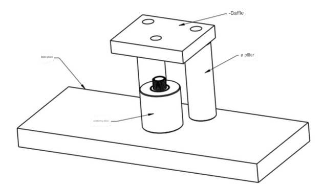
Design Points:
The image above illustrates the typical layout of punching tooling. The base plate securely attaches to the punch machine’s workbench, while the positioning block is employed to stabilize the product. The precise configuration is tailored to the specific product requirements. The central point allows for safe and effortless handling and placement of the product, while the baffle aids in separating the product from the punching knife.
The pillars serve to secure the baffle in place, and the assembly positions and dimensions of these components can be customized to accommodate the product’s unique characteristics.
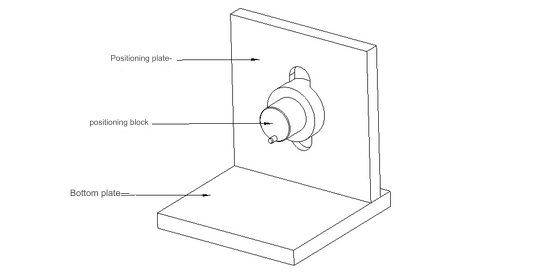
06 Welding tooling
The primary function of welding tooling is to secure the precise positioning of each component within the welding assembly and ensure the consistent sizing of each part. The core structure consists of a positioning block, custom-designed to match the specific structure of the cnc machined aluminum parts. Importantly, when positioning the product on the welding tooling, it is crucial to avoid creating a sealed space to prevent any adverse impact on the part sizes due to excessive pressure during the welding and heating process.
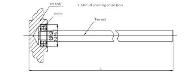
07 polishing fixture
08 Assembly tooling
The primary function of assembly tooling is to provide support for positioning during the assembly of components. The design concept is to enhance the ease of picking up and placing products according to the assembly structure of the components. It is essential to ensure that the product’s appearance remains undamaged during assembly and that it can be covered during use. Protect the product by utilizing cotton cloth, and consider using non-metallic materials such as white glue when selecting materials.
09 Pad printing, laser engraving tooling
Design Points:
Design the positioning structure of the tooling according to the engraving requirements of the actual product. Pay attention to the convenience of picking and placing the product, and the protection of the product appearance. The positioning block and the auxiliary positioning device in contact with the product should be made of white glue and other non-metallic materials as much as possible.
Anebon have the most advanced production equipment, experienced and qualified engineers and workers, recognized quality control systems and a friendly professional sales team pre/after-sales support for China wholesale OEM Plastic ABS/PA/POM CNC Metal Lathe CNC Milling 4 Axis/5 Axis CNC machining parts, CNC turning parts. Currently, Anebon is seeking ahead to even bigger cooperation with abroad customers according to mutual gains. Please experience free of charge to get in touch with us for more specifics.
2022 High quality China CNC and Machining, With a team of experienced and knowledgeable personnel, Anebon’s market covers South America, the USA, the Mid East, and North Africa. Many customers have become friends of Anebon after good cooperation with Anebon. If you have the requirement for any of our products, remember to contact us now. Anebon will look forward to hearing from you soon.
Post time: Feb-26-2024