
Mechanics is a rigorous and practical subject
As far as the drawings are concerned, you can’t go wrong.
If there is a mistake in one place, the actual application will be completely wrong.
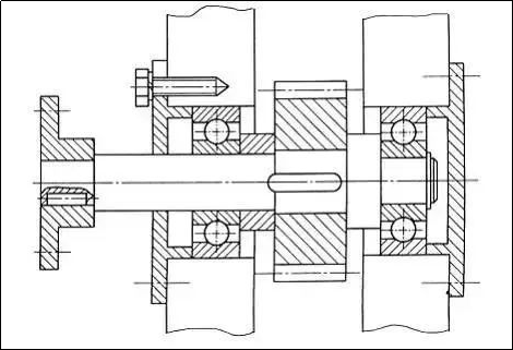
test you
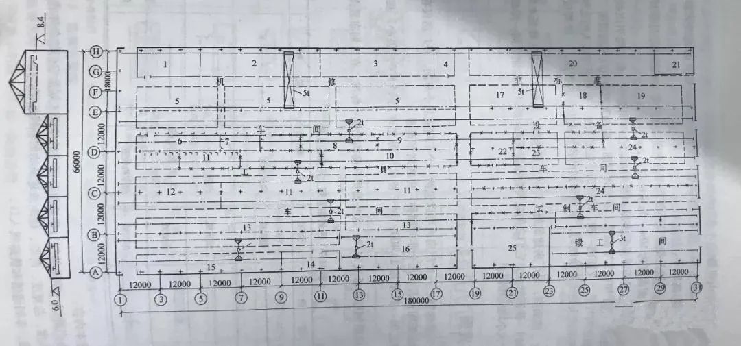
Can you see the error in this diagram?
Types of mechanical drawing
There are several types of mechanical drawing: schematic diagrams and parts drawings. BOM lists. Once you know the type of drawing, you can determine what it represents and what it means. How much expression is there?
How to read mechanical drawings?
Clarify what type of drawing it is: an assembly drawing or schematic diagram. It could also be a parts drawing or BOM list. Different types of drawing have different information, and their emphasis is different.
Everyone follows the same national drawing standards, even though the drawings are the same. A drawing is created for the public to view. It will lose meaning if it’s too complicated, has too many locations, or if other people cannot understand it. Look at the title bar in the lower right corner to see the name of the object, the number, the quantity, the material (if applicable), the proportion, the unit, and any other relevant information.
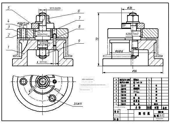
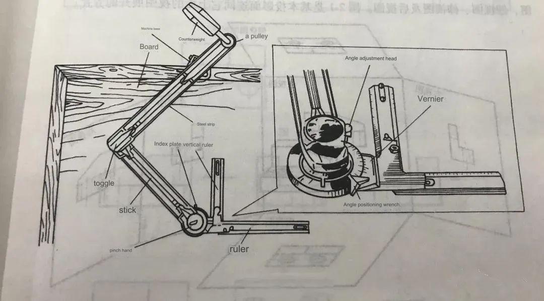
Drawing Example
Determine the view direction. Standard drawings usually have at least one. The idea of a view is derived from the projections of drawing geometry. This concept of three views must be understood to understand drawings.
The object’s shape can be expressed using the projection principle and it can be placed anywhere in the quadrant. In general, the object must be placed in the first four-square to get the projection. This method is known as the first-angle projection method. The second, third, and fourth-angle projection methods are also possible.
In Europe (such as in the United Kingdom and Germany), this method is commonly used. The third-angle method is used by the United States, Japan, and other countries.
This is the main point of the view. It requires spatial imagination and accumulation. The joke says that if the product itself cannot be restored then it will be embarrassing to “dig a well and build a chimney”. shape.
You can get an idea of the size by taking a quick look. You will need to check it out when you use it if you are a producer.
You can now be considered a layman if you’ve read the drawings. You can stop at this point if you do not want to get into the details. Mechanical drawing information is much more than just that.
Mechanical Drawings
Mechanical drawings (these drawings are standard processing drawings for products) show the structure, material, accuracy, and dimensions of a product. All the design data for a component, machine or part.
The drawings still contain a great deal of information, even though I had seen the materials and structural components before entering the industry. The mechanical design manual is thousands of pages long, since almost all the mechanical information is contained in the drawings. Every dimension and expression is given a level of importance, and all of them represent a great deal of basic knowledge. The amount of information you can comprehend depends on your personal accumulation.
Accuracy in product drawings
Mechanical dimensions, such as the diameter of an cylinder, are more than just a measurement. It doesn’t matter if the size or tolerance are marked (+-0.XX). This is what mechanical (dimensional accuracy) means. It is always a good idea to have it.
Due to the large quantity of mechanical parts produced, it is important that the sizes are controlled within a range. Components also have geometric tolerences, which exist whether or not they are marked. National standards stipulate unmarked accuracy (tolerance), and some drawing requirements state that accuracy is essential to mechanical parts. This requires a certain accumulation. Add QQ1624392196 if you want to avoid the status quo and learn UG CNC Programming.
The drawings show the process of making the product
Process is simply how to manufacture or assemble this machining part. Mechanical drawings may not directly express information about the manufacturing process, but they still contain the fundamental process. If a part cannot be processed, it is of no use to design it. The designer must have thought about how to process the part, and this will be reflected in the drawings.
Surface roughness of product as shown in the drawing
The roughness of the surface determines its use and limits the processing requirements. Different processing methods can achieve different roughness; for instance, the size and position tolerances of an element, or its shape.
Heat Treatment of Products
Heat treatment is necessary to make processing possible and ensure that the performance meets user requirements. Heat treatment is also related to the materials selected and the processing technology.
Product surface treatment
Surface treatment is usually mentioned in technical requirements. It also has some relationship to the material.
42 Basic mechanical drawing skills
1. The paper formats can be classified into five types based on size. Drawing format codes include A0,A1, A2,A3, and A4. A title bar must appear in the lower-right corner of the frame. The text of the title bar should be aligned with the direction in which the image is viewed.
2. Eight types of graph lines are available: thick solid line (thick solid line), thin solid line (thin solid line), wavy line (double polyline), dashed line (thin dot-dash), thick dotdash, and double-dash.
3. The visible contours on the machine parts have thick solid lines. The invisible contours, however, are drawn using dotted lines. Dimension lines and dimension lines also use solid lines. And the symmetry center and axis is drawn with thin dots. . The thickness of the thick solid, dashed and thin lines is approximately 1/3 the thickness of the thin solid.
4. The ratio between the size of the image and the size of the graphic is called the proportion.
5. A ratio of 1:2 is when the physical size is double the size graphic. This is called a reduction.
6. The ratio 2:1 is an enlargement of the size.
7. You should always try to draw using the ratio of the value that was originally drawn. You can use an enlargement/reduction ratio if necessary. For example, a 1:2 ratio is a reduction and a 2:1 ratio is an enlargement. The actual dimensions of machine parts must be indicated on the drawing, regardless of which scale you use.
8. Chinese characters, numbers, and letters must be written in neat fonts with clear strokes and evenly spaced. Chinese characters must be written using the Long Song style.
9. Dimensioning is composed of three components: dimension lines, dimension limits and dimension numbers.
10. In dimensioning, R is the circle radius; f is the circle diameter; and Sf is ball diameter.
11. The dimensions shown on the drawing correspond to the dimensions of the part. If the measurements are in millimeters then no code or name will be required.
12. The direction of the number at the start of the standard horizontal dimension should be upwards; for vertical dimensions, it should be left. Angle sizes are always written horizontally. When a drawing line crosses a number, it must be broken.
13. The slope is the angle of inclination between the oblique and horizontal lines, which can be represented by a symbol. The inclination of the symbol must match the inclination of the slope when marking. The taper directions marked are consistent.
14. The slope of the taper is indicated by the symbol “1″ and “1:5″.
15. In plane graphics, line segments can be classified into three types: known segment, intermediate segment, and connecting segment. The order of drawing the line segments should be known line segments followed by intermediate line segments and then connecting line segments.
16. A line segment that has a fixed length and a positioning size known is called a known segment. An intermediate line segment is a segment with a size fixed but a positioning size incomplete.
17. The projection plan where the left view appears is known as the side projection, also called the side and represented by the W.
18. The rule for three-view projection is that main view, top view, and left view must be the same size.
19. The dimensions of a part are measured in three different directions: height, width, and length. The top view only shows the width and length of the component, while the front view only shows the length and height.
20. The six directions of a part are: left, right (front and back), up, down (left), and forward. In the main view only the left, right, up and down directions can be reflected. In the top view only the left, right, front and back directions can be reflected. Left orientation: Only the front, back, upper, and lower orientations of the part can be reflected in the left view.
21. The three basic views are the main view, top and left views.
22. There are three other views besides the basic one: right view, bottom view, and rear view.
23. The cross-sectional views can be classified into three different types, depending on the size of the cutting area: the full cross-sectional, the half cross sectional, and the partial cross-sectional.
24. Section drawings can be classified into five different types of cutting: complete section, half-section, partial section (step section), and combined section.
25. Three parts are included in the labeling for the sectional views: 1. The symbol that indicates the position of cutting plane (section lines), with letters on both ends. 2. The arrow which indicates the direction of projection. 3. The words “x —-x”.
26. Ignore all cross-sectional labels, as they indicate that the cutting plane has been cut through the symmetry of the machine part.
27. Section drawings can be used to show the internal shape of a part. Sections are divided into solid and hollow sections.
28. The difference between coincident and removed sections is that coincident means a part drawn within the view outline while removed section is a part drawn outside.
29. Graphics in the drawing are only able to express the part’s structural shape. The dimensions on the drawing should be used to determine the actual size of the cnc machined component.
30. Dimensional basis is the name given to numbers that are marked with dimensions. In each dimension of length, width and hight of machine parts there is at least one dimensional base.
31. Five elements make up a thread: thread profile, diameter (pitch), lead (number of threads), and direction of rotation.
32. The outer and inner ribs can only be screwed into each other if the diameter, pitch and number of threads of both ribs is consistent.
33. Standard threads are threads that have a profile that meets national standards, but do not have a diameter or pitch. Non-standard threads are threads with a profile that does not meet the national standard. Threads are threads when their profile is in compliance with national standards, but they don’t meet the national standard for diameter and pitch. Special thread.
34. The method prescribed for drawing external threads is as follows: the major size is represented by ______, the minor is represented _d1_ and the termination is represented with a thick, solid line.
35. The major diameter of an internal thread in the cross-sectional view is represented as _D__________. The minor diameter is shown by _D1___ and the termination line by a thick, solid line. Thick solid lines are used to represent the major diameter of invisible threaded holes as well as their minor diameter and termination line.
36. Bolt connections, stud connectors and screw connectors are all common threaded connections.
37. Keys that are commonly used include flat keys and semicircular, hook wedge, splines, and hook wedge keys.
38. According to the direction in which the gear is oriented, cylindrical gears are divided into spur gears (also called helical gears), herringbone gears (also known as a helical gear) and herringbone gears.
39. The recommended method for drawing the gear teeth part is as follows: the top circle of the tooth is drawn using a thick, solid line. The index circle uses a fine, dotted line. The root circle in the section view is shown with a thick, solid line.
40. If the roughness is similar on most surfaces, then the roughness code should be placed in the upper-right corner, followed by the two remaining words.
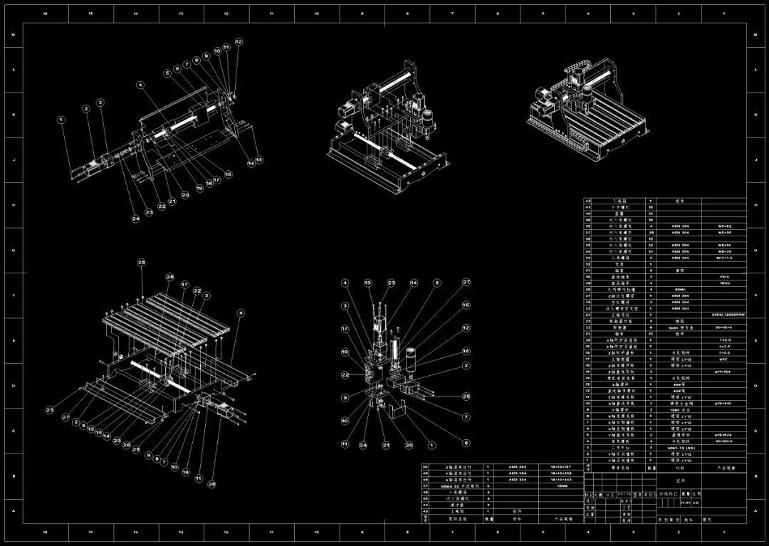
41. The complete assembly drawing should consist of four parts: a set views, 2 dimensions necessary, 3 technical requirements and 4 a column with part numbers and details.
42. Dimensions in the assembly drawing includes 1 specification dimension 2 assembly dimensions 3 Installation dimensions 4 Overall dimensions 5 other dimensions.
Anebon provide excellent toughness in excellent and advancement, merchandising, gross sales and promoting and operation for OEM/ODM Manufacturer Precision Iron Stainless Steel. Since the manufacturing unit founded, Anebon have now committed into the progress of new goods. Along with the social and economic pace, we’ll continue to carry forward the spirit of “high excellent, efficiency, innovation, integrity”, and stay with the operating principle of “credit initially, customer 1st, good quality excellent”. Anebon will produce a excellent foreseeable future in hair output with our companions.
OEM/ODM Manufacturer China Casting and Steel Casting, The design, processing, purchasing, inspection, storage, assembling process are all in scientific and effective documentary process , increasing usage level and reliability of our brand deeply, which makes Anebon become superior supplier of the four major product categories, such as CNC machining, CNC milling parts, CNC turning and metal castings.
If you want to know more and have product inquiries, please contact info@anebon.com
Post time: Dec-27-2023