
The accuracy of mechanical parts’ geometric parameters is influenced by both dimensional error and shape error. Mechanical part designs often specify dimensional tolerances and geometric tolerances simultaneously. Although there are differences and connections between the two, the accuracy requirements of geometric parameters determine the relationship between geometric tolerance and dimensional tolerance, depending on the mechanical part’s usage conditions.
1. Several tolerance principles regarding the relationship between dimensional tolerances and geometric tolerances
Tolerance principles are regulations that determine whether dimensional tolerances and geometric tolerances can be used interchangeably or not. If these tolerances cannot be converted into each other, they are considered independent principles. On the other hand, if conversion is allowed, it is a related principle. These principles are further classified into inclusive requirements, maximum entity requirements, minimum entity requirements, and reversible requirements.
2. Basic terminology
1) Local actual size D al, d al
The distance measured between two corresponding points on any normal section of an actual feature.
2) External action size D fe, d fe
This definition refers to the diameter or width of the largest ideal surface that is externally connected to the actual interior surface or the smallest ideal surface that is externally connected to the actual external surface at a given length of the feature being measured. For associated features, the axis or center plane of the ideal surface must maintain the geometric relationship given by the drawing with the datum.
3) In vivo action size D fi, d fi
The diameter or width of the smallest ideal surface in body contact with the actual inner surface or the largest ideal surface in body contact with the actual outer surface at a given length of the feature being measured.
4) Maximum physical effective size MMVS
The maximum physical effective size refers to the external effect size in the state where it is most effective physically. When it comes to the inner surface, the maximum effective solid size is calculated by subtracting the geometric tolerance value (indicated by a symbol) from the maximum solid size. On the other hand, for the outer surface, the maximum effective solid size is calculated by adding the geometric tolerance value (also indicated by a symbol) to the maximum solid size.
MMVS= MMS± T-shape
In the formula, the outer surface is represented by a “+” sign, and the inner surface is represented by a “-” sign.
5) Minimum physical effective size LMVS
The minimum effective size of an entity refers to the size of the body when it is in a minimum effective state. When referring to the inner surface, the minimum physical effective size is calculated by adding the geometric tolerance value to the minimum physical size (as indicated by a symbol in a picture). On the other hand, when referring to the outer surface, the minimum effective physical size is calculated by subtracting the geometric tolerance value from the minimum physical size (also indicated by a symbol in a picture).
LMVS= LMS ±t-shape
In the formula, the inner surface takes the “+” sign, and the outer surface takes the “-” sign.

3. Principle of independence
The principle of independence is a tolerance principle used in engineering design. This means that the geometric tolerance and dimensional tolerance specified in a drawing are separate and have no correlation with each other. Both tolerances have to meet their specific requirements independently. If the shape tolerance and dimensional tolerance follow the principle of independence, their numerical values should be marked on the drawing separately without any additional markings.
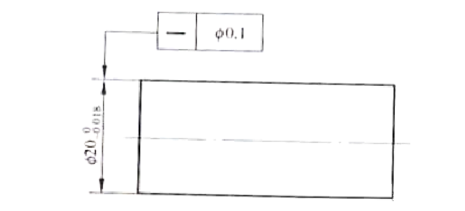
In order to ensure the quality of the parts presented in the figure, it is important to consider the dimensional tolerance of the shaft diameter Ф20 -0.018 and the straightness tolerance of the axis Ф0.1 independently. This means that each dimension must meet the design requirements on its own, and therefore they should be inspected separately.
The shaft diameter should fall between the range of Ф19.982 to 20, with an allowed straightness error between the range of Ф0 to 0.1. Although the maximum value of the shaft diameter’s actual size may extend to Ф20.1, it doesn’t need to be controlled. The principle of independence applies, meaning the diameter does not undergo comprehensive inspection.
4. Principle of tolerance
When a symbol picture appears after the dimensional limit deviation or tolerance zone code of a single element on a drawing, it means that the single element has tolerance requirements. To meet containment requirements, the actual feature must comply with the maximum physical boundary. In other words, the external acting size of the feature must not exceed its maximum physical boundary, and the local actual size must not be smaller than its minimum physical size.
The figure indicates that the value of dfe should be less than or equal to 20mm, while the value of dal should be greater than or equal to 19.70mm. During inspection, the cylindrical surface will be deemed qualified if it can pass through a full-shape gauge with a diameter of 20mm and if the total local actual size measured at two points is greater than or equal to 19.70mm.
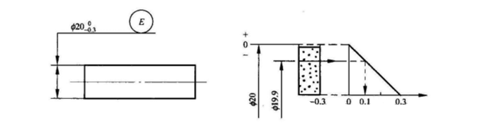
The tolerance requirement is a tolerance requirement that simultaneously controls the actual size and shape errors within the dimensional tolerance range.
5. Maximum entity requirements and their reversibility requirements
On the drawing, when a symbol picture follows the tolerance value in the geometric tolerance box or the reference letter, it means that the measured element and the reference element adopt the maximum physical requirements. Suppose the picture is labeled after the symbol picture after the geometric tolerance value of the measured element. In that case, it means that the reversible requirement is used for the maximum solid requirement.
1) The maximum entity requirement applies to the measured elements
When measuring a feature, if a maximum solidity requirement is applied, the geometric tolerance value of the feature will be given only when the feature is in its maximum solid shape. However, if the actual contour of the feature deviates from its maximum solid state, meaning that the local actual size is different from the maximum solid size, the shape and position error value can exceed the tolerance value given in the maximum solid state, and the maximum excess amount will be equal to the maximum solid state. It’s important to note that the dimensional tolerance of the measured element should be within its maximum and minimum physical size, and its local actual size should not exceed its maximum physical size.
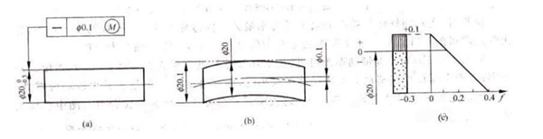
The figure illustrates the straightness tolerance of the axis, which adheres to the highest physical requirement. When the shaft is in its maximum solid state, the straightness tolerance of its axis is Ф0.1mm (Figure b). However, if the actual size of the shaft deviates from its maximum solid state, the permissible straightness error f of its axis can be increased accordingly. The tolerance zone diagram provided in Figure C shows the corresponding relationship.
The diameter of the shaft should be within the range of Ф19.7mm to Ф20mm, with a maximum limit of Ф20.1mm. To check the shaft’s quality, first measure its cylindrical outline against a position gauge that conforms to the maximum physical effective boundary size of Ф20.1mm. Then, use the two-point method to measure the local actual size of the shaft and ensure that it falls within the acceptable physical dimensions. If the measurements meet these criteria, the shaft can be deemed qualified.
The tolerance zone’s dynamic diagram illustrates that if the actual size decreases from the maximum solid state by Ф20mm, the allowable straightness error f value is allowed to increase accordingly. However, the maximum increase should not exceed the dimensional tolerance. This enables the transformation of the dimensional tolerance into the shape and position tolerance.
2) Reversible requirements are used for maximum entity requirements
When the requirement for reversibility is applied to the maximum solidity requirement, the actual contour of the feature being measured must conform to its maximum solidity effective boundary. If the actual size deviates from the maximum solid size, the geometric error is allowed to exceed the given geometric tolerance value. Additionally, if the geometric error is less than the given geometric difference value in the maximum solid state, the actual size can also exceed the maximum solid-state dimensions, but the maximum allowable excess is a dimensional commonality for the former and a given geometric tolerance for the latter.
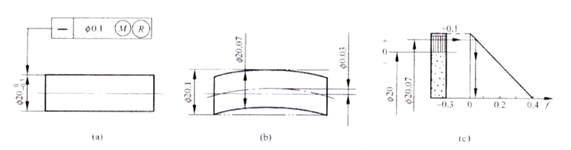
Figure A is an illustration of the use of reversible requirements for the maximum solid requirement. The axis should satisfy d fe ≤ Ф20.1mm, Ф19.7 ≤ d al ≤ Ф20.1mm.
The formula below explains that if the actual size of a shaft deviates from the maximum solid state to the minimum solid state, the straightness error of the axis can reach the maximum value, which equals the straightness tolerance value of 0.1mm given in the drawing plus the size tolerance of the shaft of 0.3mm. This results in a total of Ф0.4mm (as shown in Figure c). If the straightness error value of the axis is less than the tolerance value of 0.1mm given on the drawing, it is Ф0.03mm, and its actual size can be larger than the maximum physical size, reaching Ф20.07mm (as shown in Figure b). When the straightness error is zero, its actual size can reach the maximum value, which equals its maximum physical effective boundary size of Ф20.1mm, thus meeting the requirement of converting geometric tolerance into dimensional tolerance. Figure c is a dynamic diagram that illustrates the tolerance zone of the relationship described above.
During the inspection, the shaft’s actual diameter is compared to the comprehensive position gauge, which is designed based on the maximum physical effective boundary size of 20.1mm. Additionally, if the actual size of the shaft, as measured using the two-point method, is greater than the minimum physical size of 19.7mm, then the part is considered qualified.
3) Maximum entity requirements apply to datum features
When applying maximum solidity requirements to datum features, the datum must conform to the corresponding boundaries. This means that when the external action size of the datum feature differs from its corresponding boundary size, the datum element is allowed to move within a certain range. The floating range is equal to the difference between the external action size of the datum element and the corresponding boundary size. As the datum element deviates from the minimum entity state, its floating range increases until it reaches the maximum.
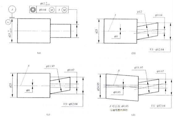
Figure A shows the coaxiality tolerance of the outer circle axis to the outer circle axis. The measured elements and datum elements adopt the maximum physical requirements at the same time.
When the element is in its maximum solid state, the coaxiality tolerance of its axis to datum A is Ф0.04mm, as shown in Figure B. The measured axis should satisfy d fe≤Ф12.04mm, Ф11.97≤d al≤Ф12mm.
When a small element is being measured, it is permissible for the coaxiality error of its axis to reach the maximum value. This value is equal to the sum of two tolerances: the coaxiality tolerance of 0.04mm specified in the drawing and the dimensional tolerance of the axis, which is Ф0.07mm (as shown in Figure c).
When the axis of the datum is at the maximum physical boundary, with an external size of Ф25mm, the given coaxiality tolerance on the drawing can be Ф0.04mm. If the external size of the datum reduces to the minimum physical size of Ф24.95mm, the datum axis can float within the dimensional tolerance of Ф0.05mm. When the axis is in the extreme floating state, the coaxiality tolerance increases to the datum dimensional tolerance value of Ф0.05mm. As a result, when the measured and datum elements are in the minimum solid state at the same time, the maximum coaxiality error can reach up to Ф0.12mm (Figure d), which is the sum of 0.04mm for coaxiality tolerance, 0.03mm for datum dimensional tolerance and 0.05mm for datum axis floating tolerance.
6. Minimum entity requirements and their reversibility requirements
If you see a symbol picture marked after the tolerance value or datum letter in the geometric tolerance box on a drawing, it indicates that the measured element or datum element must meet the minimum physical requirements, respectively. On the other hand, if there is a symbol after the geometric tolerance value of the measured element, it means that the reversible requirement is used for the minimum entity requirement.
1) Minimum entity requirements apply to the requirements under the test
When using the minimum entity requirement for a measured element, the actual outline of the element should not exceed its effective boundary at any given length. Additionally, the local actual size of the element should not exceed its maximum or minimum entity size.
If the minimum solid requirement is applied to a measured feature, the geometric tolerance value is given when the feature is in the minimum solid state. However, if the actual contour of the feature deviates from its minimum solid size, the shape and position error value can exceed the tolerance value given in the minimum solid state. In such cases, the active size of the measured feature should not exceed its minimum solid, effective boundary size.
2) Reversible requirements are used for minimum entity requirements
When applying the reversible requirement to the minimum solid requirement, the measured feature’s actual outline should not exceed its minimum solid, effective boundary at any given length. Additionally, its local actual size should not exceed the maximum solid size. Under these conditions, not only is the geometric error allowed to exceed the geometric tolerance value given in the minimum physical state when the actual size of the measured element deviates from the minimum physical size, but it is also allowed to exceed the minimum physical size when the actual size is different, provided the geometric error is smaller than the given geometric tolerance value.
The cnc machined requirements for minimum solid and its reversibility should only be used when the geometric tolerance is used to control the associated center feature. However, whether to use these requirements or not depends on the specific performance requirements of the element.
When the given geometric tolerance value is zero, the maximum (minimum) solid requirements and their reversible requirements are referred to as zero geometric tolerances. At this point, the corresponding boundaries will change while other explanations remain unchanged.

7. Determination of geometric tolerance values
1) Determination of injection shape and position tolerance values
In general, it is recommended that tolerance values should follow a specific relationship, with shape tolerance being smaller than the position tolerance and the dimensional tolerance. However, it’s important to note that in unusual circumstances, the straightness tolerance of the axis of the slender shaft may be much larger than the dimensional tolerance. The position tolerance should be the same as the dimensional tolerance and is often comparable to symmetry tolerances.
It is important to ensure that the positioning tolerance is always greater than the orientation tolerance. The positioning tolerance may include the requirements of the orientation tolerance, but the opposite is not true.
Furthermore, the comprehensive tolerance should be greater than the individual tolerances. For instance, the cylindricity tolerance of the cylinder surface can be greater than or equal to the straightness tolerance of the roundness, prime line, and axis. Similarly, the flatness tolerance of the plane should be greater than or equal to the straightness tolerance of the plane. Lastly, the total runout tolerance should be greater than the radial circular runout, roundness, cylindricity, straightness of the prime line and axis, and the corresponding coaxiality tolerance.
2) Determination of unindicated geometric tolerance values
In order to make the engineering drawings concise and clear, it is optional to indicate the geometric tolerance on the drawings for the geometric accuracy that is easy to ensure in general machine tool processing. For elements whose form tolerance requirements are not specifically stated on the drawing, the form and position accuracy is also required. Please refer to the implementation regulations of GB/T 1184. Drawing representations without tolerance values should be noted in the title block attachment or in the technical requirements and technical documents.
High-quality auto spare parts, milling parts, and steel-turned parts are made in China, Anebon. Products of Anebon have obtained more and more recognition from foreign clients and established long-term and cooperative relationships with them. Anebon will provide the best service for every customer and sincerely welcome friends to work with Anebon and establish mutual benefits together.
Post time: Apr-16-2024