
Turning Tool
The most common tool in metal cutting is the turning tool. Turning tools are used to cut outer circles, holes in the center, threads, grooves, teeth, and other shapes on lathes. Its main types are shown in Figure 3-18.
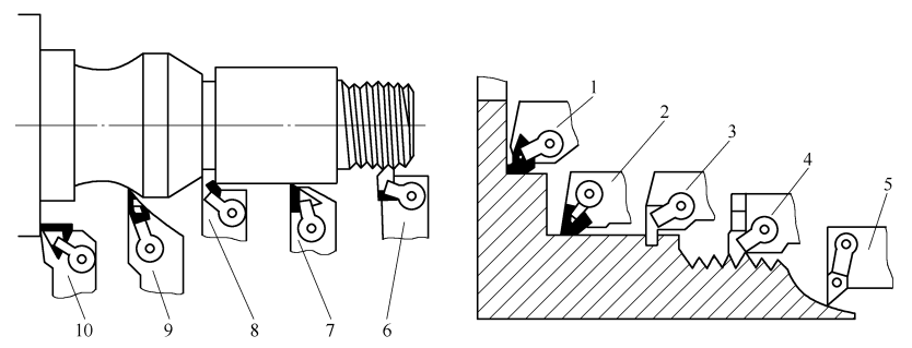
Figure 3-18 Main types of turning tools
1. 10—End turning tool 2. 7—Outer circle (inner hole turning tool) 3. 8—Grooving tool 4. 6—Thread turning tool 5. 9—Profiling turning tool
Turning tools are classified based on their structure into solid turning, welding turning, machine clamp turning, and indexable tools. Indexable turning tools are becoming more popular due to their increased use. This section focuses on introducing design principles and techniques for indexable and welding turning tools.
1. Welding tool
The welding turning tool is made up of a blade of a specific shape and holder connected by welding. Blades are usually made from different grades of carbide material. The tool shanks are generally 45 steel and sharpened to suit specific requirements during use. Quality of the welding turning tools and their use are dependent on the blade grade, the blade model, the tool geometric parameters and the shape and size the slot. Grinding quality, etc. Grinding quality, etc.
(1) There are advantages and disadvantages to welding turning tools
It is widely used because of its simple, compact structure; high tool stiffness; and good vibration resistance. It also has many disadvantages, including:
(1) The cutting performance of the blade is poor. The cutting performance of the blade will be reduced after it has been welded at a high temperature. The high temperature used for welding and sharpening causes the blade to be subjected internal stress. Since the linear extension coefficient of the carbide is half that of the tool body, this can cause cracks to appear in the carbide.
(2) The tool holder is not reusable. Raw materials are wasted because the tool holder can’t be reused.
(3) The auxiliary period is too long. The tool changing and setting takes a lot of time. This is not compatible with the demands of CNC machines, automatic machining systems, or automatic machine tools.
(2) Type of tool holder groove
For welded turning tools, tool shank grooves should be made according to the shape and size of the blade. The tool shank grooves include through grooves, semi-through grooves, closed grooves, and reinforced semi-through grooves. As shown in Figure 3-19.
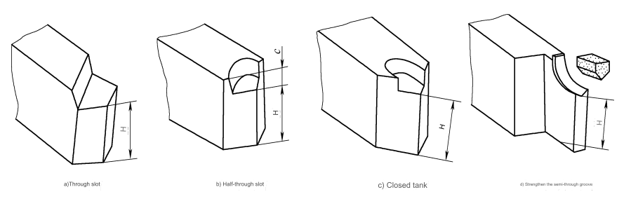
Figure 3-19 Tool holder geometry
The tool holder groove must meet the following requirements to ensure quality welding:
(1) Control the thickness. (1) Control the thickness of cutter body.
(2) Control the gap between blade and tool holder groove. The gap between blade and tool holder groove shouldn’t be too big or small, usually 0.050.15mm. The arc joint should be as uniform as possible and the maximum local gap should not exceed 0.3mm. Otherwise, the strength of the weld will be affected.
(3) Control the surface-roughness value of tool holder groove. The tool holder groove has a surface roughness of Ra=6.3mm. The blade surface should be flat and smooth. Before welding, the groove of the tool holder should be cleaned if there is any oil. To keep the surface of the welding area clean, you can use sandblasting or alcohol or gasoline to brush it.
Control the blade’s length. In normal circumstances, a blade placed in the toolholder groove should protrude by 0.20.3mm to allow for the sharpening. The tool holder groove may be made longer by 0.20.3mm than the blade. After welding, the tool body is then welded. For a neater appearance, remove any excess.
(3) The blade brazing process
Hard solder is used to weld cemented carbide blades (hard solder is refractory or brazing material that has a melting temperature higher than 450degC). The solder is heated up to a molten condition, which is usually 3050degC above the melting point. The flux protects the solder from penetration and diffusion on the surface of the machined components. It also allows the interaction of the solder with the welded component. The melting action makes the carbide blade firmly weld into the slot.
Many brazing heating techniques are available, such as gas flame welding and high frequency welding. Electric contact welding is the best heating method. The resistance at the point of contact between the copper block, and the cutter head is the highest, and this is where a high temperature will be generated. The cutter body first becomes red and then the heat is transferred to the blade. This causes the blade to slowly heat up and gradually rise in temperature. Preventing cracks is important.
The blade is not “overburned” because the power is shut off as soon as the material melts. Electric contact welding has been proven to reduce blade cracks and desoldering. Brazing is easy and stable, with a good quality. The brazing process is less efficient than high-frequency welds, and it’s difficult to braze tools with multiple edges.
The quality of brazing is affected by many factors. The brazing material, flux and heating method should be chosen correctly. For the carbide brazing tool, the material must have a melting point higher than the temperature of cutting. It is a good material for cutting because it can keep the blade’s bonding strength while maintaining its fluidity, wettability and thermal conductivity. The following brazing materials are commonly used when brazing cemented-carbide blades:
(1) The melting temperature of pure copper or copper-nickel alloy (electrolytic) is approximately 10001200degC. The allowed working temperatures are 700900degC. This can be used with tools that have heavy workloads.
(2) Copper-zinc or 105# filler metal with a melting temperature between 900920degC & 500600degC. Suitable for medium-load tooling.
The melting point of the silver-copper alloy is 670820. Its maximum working temperature is 400 degrees. However, it is suitable for welding precision turning tools with low cobalt or high titanium carbide.
The quality of brazing is greatly affected by the selection and application of flux. The flux is used to remove oxides on the surface of a workpiece that will be brazed, increase the wettability and protect the weld from oxidation. Two fluxes are used to braze carbide tools: dehydrated Borax Na2B4O2 or dehydrated Borax 25% (massfraction) + boric Acid 75% (massfraction). Brazing temperatures range from 800 to 1000degC. Borax can be dehydrated by melting the borax, then crushing it after cooling. Sift. When brazing YG tools, dehydrated borax is usually better. You can achieve satisfactory results when brazing YT tools using the formula dehydrated borax (massfraction) 50% + boric (massfraction) 35% + dehydrated potassium (massfraction) fluoride (15%).
The addition of potassium fluoride will improve the wettability and melting ability of titanium carbide. In order to reduce welding stress when brazing high-titanium alloys (YT30 and YN05), a low temperature between 0.1 and 0.5mm is commonly used. As a compensation gasket between the blades and the tool holders, carbon steel or iron-nickel is often used. To reduce thermal stress, the blade should be insulated. Usually the turning tool will be placed in a furnace with a temperature of 280°C. Insulate for three hours at 320degC, and then cool down slowly either in the furnace, or in asbestos or straw ash powder.
(4) Inorganic bonding
Inorganic bonding uses phosphoric solution and inorganic copper powder, which combine chemistry, mechanics, and physics to bond blades. Inorganic bonding is easier to use than brazing and does not cause internal stress or cracks in the blade. This method is particularly useful for blade materials that are difficult to weld, such as ceramics.
Characteristic operations and practical cases of machining
4. Selecting the angle of edge inclination and bevel cutting
(1)Bevel cutting is a concept that has been around for a long time.
Right-angle cutting is cutting in which the cutting blade of the tool is parallel to the direction the cutting motion will take. Bevel cutting is when the cutting edge of the tool is not perpendicular with the direction of the cutting motion. As a convenience, the effect of the feed can be ignored. Cutting that is perpendicular with the main movement speed or the edge inclination angles lss=0 are regarded as right angle cutting. This is shown in Figure 3-9. Cutting that isn’t perpendicular with the main movement speed or edge inclination angles lss0, is called oblique angle-cutting. For example, As shown in Figure 3-9.b, when only one cutting edge is cutting, this is known as free cutting. Bevel cutting is most common in metal cutting.
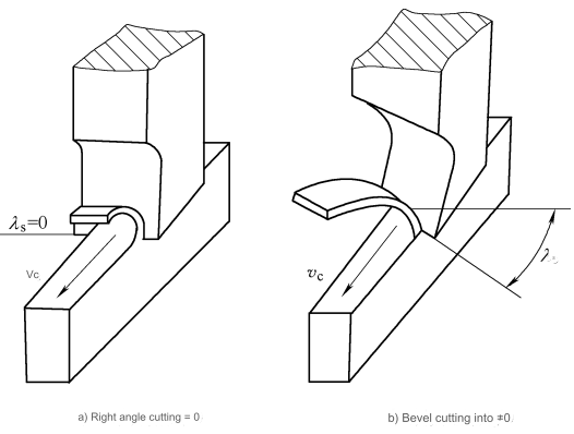
Figure 3-9 Right angle cutting and bevel cutting
(2) The influence of bevel cutting on the cutting process
1. Influence the direction of chip outflow
Figure 3-10 shows that an external turning tool is used to turn a pipe fitting. When only the main cutting edge participates in the cutting, a particle M in the cutting layer (assuming it is the same height as the center of the part) becomes a chip under the extrusion in front of the tool and flows out along the front. The relationship between the chip flow direction and the edge inclination angle is to intercept a unit body MBCDFHGM with the orthogonal plane and the cutting plane and the two planes parallel to them through point M.
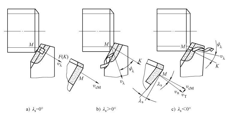
Figure 3-10 Effect of λs on flow chip direction
MBCD is the base plane in Figure 3-11. When ls=0, MBEF is the front in Figure 3-11, and plane MDF is an orthogonal and normal plane. Point M is now perpendicular the cutting edge. When the chips are ejected, M is a component of velocity along the direction of the cutting edge. The MF is perpendicularly parallel to the cutting edge. As shown in Figure 3-10a, at this point, the Chips are curved into a spring-like shape or they flow in a straight line. If ls has a positive value then the MGEF plane is in front and the main movement cutting speed vcM is not parallel to the cutting edge MG. The particle M velocity cnc turning components vT relative to the tool in the direction of the cutting edge points towards the MG. When point M is transformed into a chip that flows out in front and is affected by vT the chip’s velocity vl will deviate from the normal plane MDK at a chip angle of psl. When ls has a large value, the chips will flow in the direction of processing the surface.
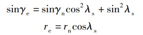
The plane MIN, as shown in Figures 3-10b and 3-11, is known as the chip flow. When ls has a negative value the velocity component vT in the direction of the cutting edge is reversed, pointing to the GM. This causes the chips to diverge from the normal plane. The flow is in the opposite direction towards the surface of the machine. As shown in Figure 3-10.c. This discussion is only about the effect of ls during free cutting. The plastic flow of the metal at the tool tip, minor cutting edge, and chip groove will all have an effect on the direction of the outflow of chips during the actual machining process of turning outer circles. Figure 3-12 shows the tapping of through-holes and closed holes. Influence of the cutting edge inclination on chip flow. When tapping a holeless thread, the value ls is positive, but when tapping one with a hole, it’s a negative value.
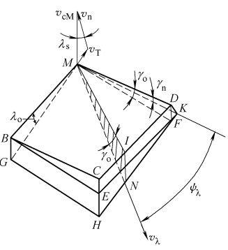
Figure 3-11 Oblique cutting chip flow direction
2. The actual rake and obtuse radii are affected
When ls = 0, in free cutting, the rake angles in the orthogonal plane and the chip flow plane are roughly equal. If ls isn’t zero, it can really affect the cutting edge sharpness and friction resistance when the chips are pushed out. In the chip flow plane, the effective rake angles ge and cutting edge obtuse radii re must be measured. Figure 3-13 compares the geometry of a normal plane that passes through the M-point of the main edge with the obtuse radii re of the chip flow plane. In the case of the sharp edge, the normal plane shows an arc formed by the obtuse radius rn. However, in the profile of the chip flow, the cutting is part an ellipse. The radius of curvature along the long axis is the actual cutting edge obtuse radius re. The following approximate formula can be calculated from the geometric relationship figures in Figures 3-11 and 3-13.
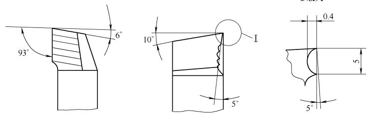
The formula above shows that re increases as the absolute value ls increases, while ge decreases. If ls=75deg, and gn=10deg with rn=0.020.15mm then ge can be as big as 70deg. re can also be as small as 0.0039mm. This makes the cutting edge very sharp, and it can achieve micro-cutting (ap0.01mm) by using a small amount of back cutting. Figure 3-14 shows the cutting position of an external tool when ls is set at 75deg. The main and secondary edges of the tool have been aligned in a straight line. The cutting edge of the tool is extremely sharp. The cutting edge is not fixed during the process of cutting. It is also tangent with the outer cylindrical surface. Installation and adjustment are easy. The tool has been used successfully for high-speed turning finishing of carbon steel. It can also be used to finish processing difficult-to-machine material such as high strength steel.
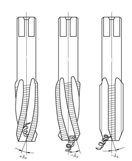
Figure 3-12 The influence of edge inclination angle on chip flow direction during thread tapping
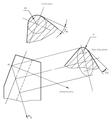
Figure 3-13 Comparison of rn and re geometries
3. Impact resistance and strength of the tool tip are affected
When ls is negative, as shown in Figure 3-15b, the tool tip will be the lowest point along the cutting edge. When the cutting edges cut into the prototype parts the first point of impact with the workpiece is the tooltip (when go has a value positive) or the front (when it is negative) This not only protects and strengthens the tip, but also helps to reduce the risk of damage. Many tools with large rake angle use negative edge inclination. They can both enhance the strength and reduce the impact on the tool tip. The back force Fp is increasing at this point.
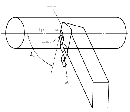
Figure 3-14 Large blade angle turning tool without fixed tip
4. Affects the stability of cutting in and out.
When ls = 0, the cutting edge cuts into and out of the workpiece almost simultaneously, the cutting force suddenly changes, and the impact is large; when ls is not zero, the cutting edge gradually cuts into and out of the workpiece, the impact is small, and the cutting is smoother. For example, large helix angle cylindrical milling cutters and end mills have sharper cutting edges and smoother cutting than old standard milling cutters. Production efficiency is increased by 2 to 4 times, and the surface roughness value Ra can reach less than 3.2 mm.
5. Cutting edge shape
The cutting edge shape of the tool is one of the basic contents of the reasonable geometric parameters of the tool. Changes in the blade shape of the tool change the cutting pattern. The so-called cutting pattern refers to the order and shape in which the metal layer to be processed is removed by the cutting edge. It affects the size of the cutting edge load, stress conditions, tool life and machined surface quality. wait. Many advanced tools are closely related to the reasonable selection of blade shapes. Among advanced practical tools, the blade shapes can be summarized into the following types:
(1) Enhance the blade shape of the cutting edge. This blade shape is mainly to strengthen the strength of the cutting edge, increase the cutting edge angle, reduce the load on the unit length of the cutting edge, and improve heat dissipation conditions. In addition to several tool tip shapes shown in Figure 3-8, there are also arc edge shapes (arc edge turning tools, arc edge hobbing face milling cutters, arc edge drill bits, etc. ), multiple sharp angle edge shapes (drill bits, etc.) )wait;
(2) An edge shape that reduces the residual area. This edge shape is mainly used for finishing tools, such as large-feed turning tools and face milling cutters with wipers, floating boring tools and ordinary boring tools with cylindrical wipers. Reamers, etc. ;
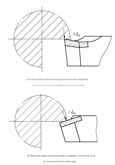
Figure 3-15 Effect of edge inclination angle on impact point when cutting tool
(3) A blade shape that reasonably distributes the cutting layer margin and smoothly discharges the chips. The characteristic of this type of blade shape is that it divides the wide and thin cutting layer into several narrow chips, which not only allows the chips to be discharged smoothly, but also increases the advance rate. Give the amount and reduce the unit cutting power. For example, compared with ordinary straight-edge cutting knives, double-stepped edge cutting knives divide the main cutting edge into three sections, as shown in Figure 3-16. The chips are also divided into three strips accordingly. The friction between the chips and the two walls is reduced, which prevents the chips from being blocked and greatly reduces the cutting force. As the cutting depth increases, the decrease rate increases, and the effect is better. At the same time, the cutting temperature is reduced and the tool life is improved. There are many tools belonging to this type of blade shape, such as step milling cutters, staggered edge milling cutters, staggered edge saw blades, chip drill bits, staggered tooth corn milling cutters, and wave edge end mills. And wheel-cut broaches, etc.;
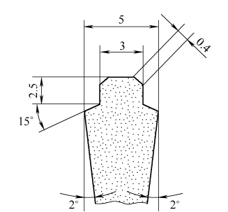
Figure 3-16 Double stepped edge cutting knife
(4) Other special shapes. Special blade shapes are blade shapes that are designed to meet the processing conditions of a part and its cutting characteristics. Figure 3-17 illustrates the front washboard shape used for processing lead-brass. The main cutting edge of this blade is shaped in multiple three-dimensional arches. Each point on the cutting edge has an inclination angle that increases from negative, to zero and then to positive. This causes the debris to be squeezed out into ribbon-shaped chips.
Anebon alyways upholds the philosophy of “Be No.1 in high-quality, be rooted on credit and trustworthiness for growth”. Anebon will keep on to serve previous and new prospects from home and overseas whole-heatedly for Ordinary Discount 5 Axis Precision Custom Rapid Prototype 5 axis cnc milling Turning Machining, At Anebon with top quality to start with as our motto, we manufacture products that are entirely made in Japan, from materials procurement to processing. This enables customers from all over the country to get used with confident peace of mind.
China fabrication processes, metal milling services and fast prototyping service. Anebon regards “reasonable prices, efficient production time and good after-sales service” as our tenet. Anebon hope to cooperate with more customers for mutual development and benefits. We welcome potential buyers to contact us.
Post time: Dec-14-2023