
A thread is a helix cut into a workpiece either from the outside or from the inside and serves several important functions. First, threads create a mechanical connection by combining an internally threaded product with an externally threaded product. This connection ensures that the different parts of the workpiece can be firmly connected to each other.
Furthermore, threads play a vital role in transmitting motion. They can convert rotary motion into linear motion and vice versa. This capability is particularly useful in many applications, such as in machinery that require linear motion to perform specific tasks.
In addition, threads offer mechanical advantages. By utilizing threads, higher mechanical performance can be achieved in every respect. This includes increased load carrying capacity, enhanced resistance to loosening or vibration, and improved power transmission efficiency.
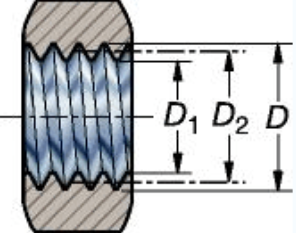
There are different thread forms, each of which determines the geometry of the thread. An important aspect of thread profile is the workpiece diameter. This includes the major diameter (the largest diameter of the thread) and the pitch diameter (the diameter at the imaginary point where the thread width is zero). These measurements are critical to ensuring that the threads fit properly and function effectively.
Understanding thread terminology is critical to using threads effectively. Some key terms include lead (the axial distance a thread travels in one complete revolution) and pitch (the distance between corresponding points on adjacent threads). Accurate measurement of lead and pitch is important to ensure accurate thread design and compatibility.
In summary, threads serve several important functions in various industries. They facilitate mechanical connections, transmit motion and provide mechanical advantages. Understanding thread profiles and related terminology is critical to using threads successfully and ensuring optimal performance.
Solving the Mystery of Pitch: Exploring Its Meaning and Calculation Method
Thread pitch is a key factor in the field of manufacturing and machining. Understanding what it means and calculating it correctly is critical to making high-quality machined parts. In this article, we’ll dive into the intricacies of thread pitch, its geometry, and how to determine it accurately. Additionally, we will introduce Anebon, a company specializing in prototype CNC machining services and custom CNC milling, offering fast and reliable online quotes for CNC machining.
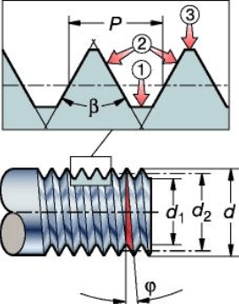
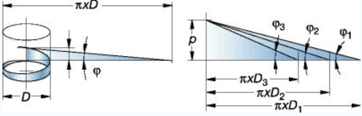
The geometry of the thread is based on the thread pitch diameter (d, D) and the pitch (P): the axial distance along the thread on the workpiece from one point on the profile to the corresponding next point. Think of it as a triangle that goes around the workpiece. This triangular structure determines the effectiveness and functionality of the threaded components. Accurate calculation of thread pitch is critical to ensure correct fit, optimal load distribution and efficient performance of machined parts.
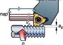
In order to accurately determine the pitch, the manufacturer uses advanced CNC machining technology. CNC machining, or computer numerical control machining, is a manufacturing process that uses computer-controlled machine tools to precisely remove material from raw materials to form machined parts. CNC Machining Online Quoting is a service offered by many professional companies that allows customers to quickly and easily obtain price estimates for their custom CNC machining parts.
Anebon is a leading company in the hardware industry, providing quality prototype CNC machining services and custom CNC milling since its inception in 2010. With a professional team of professionals and state-of-the-art equipment, Anebon provides efficient, high-quality products. Standard machines imported from Japan. Their CNC mills and lathes as well as surface grinders enable them to deliver outstanding product precision and quality. Additionally, Anebon is ISO 9001:2015 certified, demonstrating their commitment to maintaining the highest production standards and customer satisfaction.
When calculating pitch, it is usually expressed in threads per inch (TPI) or millimeters. For metric threads, the pitch is specified as the distance in millimeters between two adjacent thread crests. Conversely, for inch-based thread systems, TPI stands for threads per linear inch. Accurately measuring thread pitch is critical to ensuring compatibility between threaded parts and avoiding potential problems such as looseness, brittleness or insufficient load distribution.
CNC machining plays a vital role in achieving accurate pitch measurement. By utilizing cutting-edge technology and precision equipment, CNC machined parts can meet the most stringent requirements and specifications. Advanced software programs enable CNC machines to perform complex thread calculations, ensuring the correct thread pitch is achieved for each unique application.
In summary, understanding the intricacies of pitch and calculating it accurately is critical to making high-quality machined parts. By utilizing prototype CNC machining services and utilizing custom CNC milling, manufacturers can achieve exceptional precision and quality in their products. Committed to excellence and with state-of-the-art equipment, companies like Anebon lead the way in providing reliable, efficient CNC machining online quote services. With precise knowledge of thread pitch, manufacturers can create threaded parts that meet the highest standards of performance and functionality.
1. Calculation and tolerance of pitch diameter of 60° tooth-shaped external thread (national standard GB197/196)
a.Calculation of pitch diameter basic size
The basic size of the pitch diameter of the thread = the major diameter of the thread – pitch × coefficient value.
Formula representation: d/DP×0.6495
Example: Calculation of pitch diameter of external thread M8 thread
8-1.25×0.6495=8-0.8119≈7.188
b. Commonly used 6h external thread pitch diameter tolerance (based on thread pitch)
The upper limit value is “0″
The lower limit is P0.8-0.095P1.00-0.112P1.25-0.118
P1.5-0.132P1.75-0.150P2.0-0.16
P2.5-0.17
The upper limit calculation formula is the basic size, and the lower limit calculation formula d2-hes-Td2 is the pitch diameter basic size-deviation-allowable deviation.
Tolerance value of 6h grade pitch diameter of M8: upper limit value 7.188 lower limit value: 7.188-0.118=7.07.
C. Commonly used 6g grade external thread pitch diameter basic deviation: (based on thread pitch)
P0.80-0.024P1.00-0.026P1.25-0.028P1.5-0.032
P1.75-0.034P2-0.038P2.5-0.042
The upper limit calculation formula d2-ges is the basic size deviation
The lower limit calculation formula d2-ges-Td2 is the basic size deviation tolerance
For example, the 6g grade pitch diameter tolerance value of M8: upper limit value 7.188-0.028=7.16 lower limit value: 7.188-0.028-0.118=7.042.
Note:
①The above thread tolerances are based on coarse threads, and the thread tolerances of fine threads are also changed accordingly, but the tolerances are only enlarged, so the control will not exceed the standard limit, so they are not marked in the table. The top came out.
②In actual production, according to the precision required by the design and the extrusion force of the thread processing equipment, the diameter of the threaded polished rod is increased by 0.04-0.08 compared with the designed thread diameter, which is the diameter of the threaded polished rod. For example, the diameter of our company’s M8 external thread 6g thread polished rod is 7.08-7.13, which is within this range.
③Considering the needs of the production process, the lower control limit of the pitch diameter of the external thread without heat treatment and surface treatment in actual production should be kept at the 6h level as much as possible.
2. Calculation and tolerance of pitch diameter of 60° internal thread (GB197/196)
a.6H level thread pitch diameter tolerance (based on thread pitch)
upper limit:
P0.8+0.125P1.00+0.150P1.25+0.16P1.5+0.180
P1.25+0.00P2.0+0.212P2.5+0.224
The lower limit value is “0″,
The upper limit calculation formula 2+TD2 is the basic size + tolerance.
For example, the pitch diameter of M8-6H internal thread is: 7.188+0.160=7.348 upper limit: 7.188 is the lower limit.
b. The formula for calculating the pitch diameter of the internal thread is the same as that of the external thread
That is, D2=DP×0.6495, that is, the pitch diameter of the internal thread is equal to the pitch diameter×coefficient value.
c.6G class thread pitch diameter basic deviation E1 (based on thread pitch)
P0.8+0.024P1.00+0.026P1.25+0.028P1.5+0.032
P1.75+0.034P1.00+0.026P2.5+0.042
Example: Upper limit of pitch diameter of M86G internal thread: 7.188+0.026+0.16=7.374
Lower limit: 7.188+0.026=7.214
The upper limit formula 2+GE1+TD2 is the basic size of pitch diameter+deviation+tolerance
The lower limit value formula 2+GE1 is pitch diameter size+deviation
3. Calculation and tolerance of major diameter of external thread (GB197/196)
a.Upper limit of 6h major diameter of external thread
That is, the thread diameter value example M8 is φ8.00, and the upper limit tolerance is “0″.
b. Tolerance of the lower limit of the major diameter of external thread 6h class (based on thread pitch)
P0.8-0.15P1.00-0.18P1.25-0.212P1.5-0.236P1.75-0.265
P2.0-0.28P2.5-0.335
Calculation formula for the lower limit of the major diameter: d-Td is the basic dimension-tolerance of the major diameter of the thread.
Example: M8 external thread 6h large diameter size: upper limit is φ8, lower limit is φ8-0.212=φ7.788
c.Calculation and Tolerance of Major Diameter 6g of External Thread
6g external thread reference deviation (based on thread pitch)
P0.8-0.024P1.00-0.026P1.25-0.028P1.5-0.032P1.25-0.024P1.75–0.034
P2.0-0.038P2.5-0.042
The upper limit calculation formula d-ges is the basic dimension of thread major diameter-reference deviation
The lower limit calculation formula d-ges-Td is the basic dimension of thread major diameter-baseline deviation-tolerance
Example: M8 external thread 6g class major diameter upper limit φ8-0.028=φ7.972.
Lower limit φ8-0.028-0.212=φ7.76
Note: ①The major diameter of the thread is determined by the diameter of the thread polished rod and the degree of wear of the thread rolling plate/roller tooth profile, and its value is inversely proportional to the upper and middle diameter of the thread. On the basis of the same blank and threading tool, the smaller the middle diameter, the larger the major diameter, and vice versa, the larger the middle diameter, the smaller the major diameter.
② For parts that require heat treatment and surface treatment, considering the relationship between processing technology and actual production, the major diameter of the thread should be controlled at the lower limit of class 6h plus 0.04mm or more. For example, for an M8 external thread, the major diameter of the rubbing (rolling) thread should be guaranteed to be above 7.83 and below 7.95.
4. Calculation and tolerance of small diameter of internal thread
a.Calculation of the basic size of the small diameter of the internal thread (D1)
Basic size of small diameter thread = basic size of internal thread – pitch × coefficient
Example: The basic size of the small diameter of the internal thread M8 is 8-1.25×1.0825=6.646875≈6.647
b. Calculation of internal thread 6H small diameter tolerance (based on thread pitch) and small diameter value
P0.8+0.2P1.0+0.236P1.25+0.265P1.5+0.3P1.75+0.335
P2.0+0.375P2.5+0.48
The lower limit deviation formula D1+HE1 of internal thread 6H class is the basic size of internal thread small diameter + deviation.
Note: The bias value is “0″ at 6H level
Calculation formula for upper limit of 6H level of internal thread=D1+HE1+TD1, that is, basic size of small diameter of internal thread + deviation + tolerance.
Example: The upper limit of the small diameter of 6H grade M8 internal thread is 6.647+0=6.647
The lower limit of the small diameter of 6H grade M8 internal thread is 6.647+0+0.265=6.912
c.Calculation of the basic deviation of the small diameter of the internal thread 6G (based on the pitch) and the value of the small diameter
P0.8+0.024P1.0+0.026P1.25+0.028P1.5+0.032P1.75+0.034
P2.0+0.038P2.5+0.042
The calculation formula for the lower limit of the small diameter of the internal thread 6G = D1 + GE1 is the basic size of the internal thread + deviation.
Example: The lower limit of the small diameter of 6G grade M8 internal thread is 6.647+0.028=6.675
The formula D1+GE1+TD1 for the upper limit value of the small diameter of the 6G grade M8 internal thread is the basic size of the internal thread + deviation + tolerance.
Example: The upper limit of the small diameter of 6G grade M8 internal thread is 6.647+0.028+0.265=6.94
Note:
①The tooth height of the internal thread is directly related to the bearing moment of the internal thread, so the blank should be within the upper limit of the 6H class as far as possible.
②During internal thread machining, the smaller the small diameter of the internal thread, the lower the efficiency of the processing tool—the tap. From the point of view of use, the smaller the small diameter, the better, but comprehensive consideration, the small diameter is generally used between the middle limit and the upper limit, if it is cast iron or aluminum, it should be used between the lower limit and the middle limit of the small diameter .
③When the small diameter of the internal thread is 6G, it can be realized as 6H. The accuracy level mainly considers the coating of the pitch diameter of the thread. Therefore, only the pitch diameter of the tap is considered during thread processing, and the small diameter is not considered. The diameter of the light hole.
5. Calculation formula of dividing head single dividing method
Single division calculation formula: n=40/Z
n: the number of circles that the dividing head should turn
Z: the equal part of the workpiece
40: fixed indexing head number
Example: Calculation for milling a hexagon
Substitute into the formula: n=40/6
Calculation: ① Simplify fractions: find the smallest divisor 2 and divide by, that is, divide the numerator and denominator by 2 at the same time to get 20/3. While reducing the score, its equal division remains the same.
② Calculation of fractions: At this point, it depends on the values of the numerator and denominator; if the numerator and denominator are large, then the calculation is performed.
20÷3=6(2/3) is the n value, that is, the dividing head should turn 6(2/3) circles. At this time, the fraction has become a fraction; the integer part of the decimal 6 is the division head should turn 6 full circles. A fraction 2/3 with a fraction can only be 2/3 of a circle and must be recalculated at this point.
③Selection and calculation of the indexing plate: the calculation of less than one circle must be realized with the help of the indexing plate of the indexing head. The first step in the calculation is to simultaneously expand the fraction by 2/3. For example: if the score is magnified 14 times at the same time, it is 28/42; if it is magnified 10 times at the same time, the score is 20/30; if it is magnified 13 times at the same time, the score is 26/39…The enlarged scale should be according to the dial Choose the number of holes on it.
At this point should pay attention to:
①The number of holes of the selected indexing plate must be divisible by the denominator 3. For example, in the above example, 42 holes are 14 times of 3, 30 holes are 10 times of 3, and 39 holes are 13 times of 3. .
②The expansion of fractions must be that the numerator and denominator are expanded at the same time, and equal division remains unchanged, for example
28/42=2/3×14=(2×14)/(3×14); 20/30=2/3×10=(2×10)/(3×10);
26/39=2/3×13=(2×13)/(3×13)
28/42 The denominator 42 is to use the 42 holes of the index number for indexing; the numerator 28 moves forward on the positioning hole of the upper wheel, and then turns over the 28 hole, that is, the 29 hole is the positioning hole of the current wheel, 20/ 30 is 10 holes forward at the rotating place of the 30-hole index plate, and the 11th hole is exactly the positioning hole of this wheel. 26/39 is the positioning hole of this wheel on the 39-hole index plate, and the 26 holes of the 27th holes are rotated forward.
When milling a hexagon (sixths), holes such as 42 holes, 30 holes, and 39 holes that can be divisible by 3 are used as scales: the operation is to rotate the handle 6 times, and then move forward on the positioning hole to be the upper wheel respectively. Turn 28+1/10+1/26+ again! The hole in the upper 29/11/27 hole is used as the positioning hole of the wheel.
Example 2: Calculation for milling a 15-tooth gear.
Substitute into the formula: n=40/15
Calculate n=2(2/3)
It is to turn 2 full circles, and then select the indexing holes that can be divisible by 3, such as 24, 30, 39, 42.51. Add 1 hole, namely 17, 21, 27, 29, 35, 37, 39, 45 holes, as the positioning hole for this wheel.
Example 3: Calculation of indexing for milling 82 teeth.
Substitute into the formula: n=40/82
Calculate n=20/41
That is: as long as the index plate with 41 holes is selected, turn 20+1 on the positioning hole of the upper wheel, that is, 21 holes are used as the positioning hole of the current wheel.
Example 4: Calculation of indexing for milling 51 teeth
Substituting the formula n=40/51, since the score cannot be calculated at this time, you can only directly select the hole, that is, select the index plate with 51 holes, and then turn the 51+1 upper wheel on the positioning hole, that is, 52 holes, as the current wheel. Positioning holes viz.
Example 5: Calculation of indexing for milling 100 teeth.
Substitute into the formula n=40/100
Calculate n=4/10=12/30
Select the 30-hole index plate in time, and then put 12+1 or 13 holes on the upper wheel positioning hole as the current wheel positioning hole.
If all the indexing discs do not reach the number of holes required for calculation, the compound indexing method should be used for calculation, which is not included in this calculation method. In actual production, gear hobbing is generally used, because the actual operation after compound indexing calculation is extremely inconvenient.
6. Calculation formula for a hexagon inscribed in a circle
① Find the opposite side of the hexagon (S surface) of the circle D
S=0.866D is diameter×0.866 (coefficient)
② Calculate the diameter (D) of the circle from the opposite side of the hexagon (S surface)
D=1.1547S opposite side×1.1547 (coefficient)
7. Calculation formula of opposite side and diagonal line of hexagon in cold heading process
① Find the opposite angle e of the opposite side (S) of the outer hexagon
e=1.13s Opposite side×1.13
② Find the opposite angle (e) from the opposite side (s) of the inner hexagon
e=1.14s Opposite side×1.14 (coefficient)
③ Obtain the material diameter of the diagonal head (D) from the opposite sides (s) of the external hexagon
The diameter (D) of the circle should be calculated according to the opposite side (s plane) of the hexagon (the second formula in 6), and the offset center value should be appropriately increased, that is, D≥1.1547s. The amount of offset from center can only be estimated.
8. Calculation formula of square inscribed in a circle
① Draw a circle (D) to find the opposite side of the square (S surface)
S=0.7071D is diameter×0.7071
② Find the circle (D) from the opposite side of the square (S surface)
D=1.414S opposite side×1.414
9. Calculation formulas for square opposite sides and opposite angles in cold heading process
① Find the opposite angle (e) from the opposite side (S) of the outer square
e=1.4s is the opposite side (s)×1.4 parameter
② Find the opposite angle (e) of the opposite side (s) of the inner square
e=1.45s is the opposite side (s)×1.45 coefficient
10. Hexagon volume calculation formula
s20.866×H/m/k means opposite side×opposite side×0.866×height or thickness.
11. Calculation formula for truncated (cone) volume
0.262H (D2+d2+D×d) is 0.262×height×(large head diameter×large head diameter+small head diameter×small head diameter+big head diameter×small head diameter).
12. Calculation formula for the volume of a sphere (such as a semicircular head)
3.1416h2(Rh/3) is 3.1416×height×height×(radius-height÷3).
13. Calculation formula for machining dimensions of internal thread taps
1. Calculation of tap major diameter D0
D0=D+(0.866025P/8)×(0.5~1.3) is the basic size of tap large diameter thread + 0.866025 pitch÷8×0.5~1.3.
Note: The selection of 0.5~1.3 should be determined according to the pitch size. The larger the pitch value, the smaller the coefficient should be used. Conversely, the smaller the pitch value, the larger the corresponding coefficient should be.
2. Calculation of tap pitch diameter (D2)
D2=(3×0.866025P)/8, that is, tap diameter=3×0.866025×pitch÷8
3. Calculation of tap diameter (D1)
D1=(5×0.866025P)/8 is tap diameter=5×0.866025×pitch÷8
Fourteen,
Calculation formula of material length for cold heading forming of various shapes
The volume formula of a known circle is diameter×diameter×0.7854×length or radius×radius×3.1416×length. That is, d2×0.7854×L or R2×3.1416×L
When calculating, the volume X÷diameter÷diameter÷0.7854 or X÷radius÷radius÷3.1416 of the required material is the length of the material.
Column formula = X/(3.1416R2) or X/0.7854d2
In the formula, X represents the volume value of the required material;
L represents the length value of the actual feeding;
R/d represents the actual feeding radius or diameter.
Anebon’s goal is to understand excellent disfigurement from the manufacturing and supply the top support to domestic and abroad clients wholeheartedly for 2022 High quality Stainless Steel Aluminum High Precision Custom Made CNC Turning Milling Machining Spare Part for Aerospace, In order to expand our international market, Anebon mainly supply our oversea customers Top quality performance mechanical parts, milled parts and cnc turning service.
China wholesale China Machinery Parts and CNC Machining Service, Anebon upholds the spirit of “innovation, harmony, team work and sharing, trails, pragmatic progress”. Give us a chance and we will be going to prove our capability. With your kind help, Anebon believe that we can create a bright future with you together.
Post time: Jul-10-2023