
What is a car slender axle?
A slender car axle is a type that’s used in cars and designed to be light. Slender axles tend to be used in vehicles with a focus on fuel efficiency and agility. They reduce the vehicle’s overall weight while improving its handling. These axles are usually made from lightweight, strong materials like aluminum or high strength steel. These axles are built to be able to handle the driving forces, such as the torque generated by the engine, and still maintain a compact, streamlined design. The slender axles are essential to the transmission of power from an engine to wheels.
Why is it easy to bend and deform when processing the slender shaft of the car?
It would be difficult to bend or deform a shaft that is so thin. The materials used to make car shafts (also known as drive shafts or axles) are usually strong and durable, such as carbon fiber composite or steel. The materials used are selected for their high strength, which is needed to resist the torque and forces generated by the transmission and engine of the car.
During manufacturing, the shafts go through various processes, such as forging and heat treatment, to maintain their rigidity and strength. These materials, along with the manufacturing techniques, prevent the shafts from bending under normal conditions. However, extreme forces such as collisions and accidents can bend or deform any part of the car, including shafts. It is vital to repair or replace any damaged parts to ensure the safe and efficient operation of your vehicle.
Machining process:
Many shaft parts have an aspect ratio of L/d > 25. The horizontal slender axis is easily bent or can even lose its stability under the influence of gravity, cutting force and top clamping forces. The stress problem on the slender shaft must be reduced when turning the shaft.
Processing method:
Reverse-feed turning is used, with a number of effective measures, such as a selection of tool geometry parameters, cutting amounts, tensioning devices, and bushing tool rests.
Analysis of Factors that Cause Bending Deformation of Turning Slender Shaft
Two traditional clamping techniques are used to turn slender shafts in lathes. One method uses one clamp with one top installation, and the other is two top installations. We will mainly focus on the clamping technique of a single clamp and a top. As shown in Figure 1.
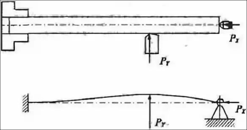
Figure 1 One clamp and one top clamping method and force analysis
The main causes of bending deformation caused by turning the slender shaft are:
(1) Cutting force causes deformation
The cutting force can be divided into three components: axial force PX (axial force), radial force PY (radial force) and tangential force PZ. When turning thin shafts, different cutting forces can have different effects on the bending deformation.
1) Influence of the radial cutting forces PY
The radial force cuts vertically through the shaft axis. The radial cutting force bends the slender shaft in the horizontal plane due to its poor rigidity. Figure shows the effect of the cutting force on the bending of the slender shaft. 1.
2) Impact of the axial cutting force (PX)
The axial force is parallel to the axis on the thin shaft and forms a bending moment in the workpiece. The axial force is not significant for general turning and can be ignored. Due to its poor rigidity, the shaft is unstable due to its poor stability. The slender shaft bends when the axial force is greater than a certain amount. As shown in the picture 2.
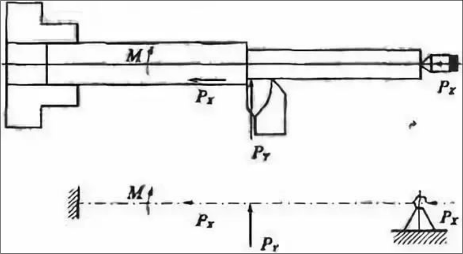
Figure 2: Effect of cutting force on axial force
(2)Cutting heat
Thermal deformation of the workpiece will occur due to the cutting heat produced by processing. The distance between the chuck, the top of the rearstock and the workpiece is fixed because the chuck is fixed. This limits the axial extension of the shaft, which results in the shaft bending due to the axial extrusion.
It is clear that improving the accuracy of machining the thin shaft is fundamentally a problem of controlling stress and thermal deformation in the process system.
Measures to Improve Machining Accuracy of Slender Shaft
To improve the accuracy of machining a slender shaft, it is necessary to take different measures according to the production conditions.
(1) Select the correct clamping method
Double-center clamping, one of the two clamping methods traditionally used to turn slender shafts, can be used to accurately position the workpiece while ensuring coaxiality. This method of clamping the slender sleeve has poor rigidity, a large bending deformation, and is susceptible to vibration. It is therefore only suitable for installations with a small length to diameter ratio, a small machining allowance and high requirements of coaxiality. Tall precision machining components.
In most cases, the machining of thin shafts is done using a clamping system consisting of one top and one clamp. In this clamping technique, however, if you have a tip that is too tight it will not only bend the shaft but also prevent it from elongating when the shaft is turned. This can cause the shaft to be squeezed axially and bent out-of-shape. The clamping surface may not be aligned with the hole of the tip, which can cause the shaft to bend after it is clamped.
When using the clamping technique of one clamp with one top, the top must use elastic living centres. After heating the slender sleeve, it can be elongated freely to reduce its bending distortion. At the same time an open steel traveler is inserted between jaws to the slender sleeve to reduce axial contact between jaws to the slender sleeve and eliminate over-positioning. Figure 3 shows the installation.
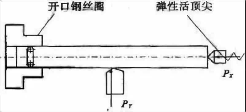
Figure 3: Improvement method using one clamp and a top clamp
Reduce the force of deformation by reducing the length of the shaft.
1) Use the heelrest and center frame
One clamp and one top are used to turn the slender shaft. To reduce the impact of radial force on the deformation caused by the slender shaft, the traditional toolrest and center frame is used. This is the equivalent of adding a support. This increases the rigidity and can reduce the impact of radial force on the shaft.
2) The slender sleeve is rotated by the axial clamping technique
It is possible to increase the rigidity and eliminate the effect of the radial force on the workpiece by using the tool rest or the center frame. It still cannot solve the problem of the axial force bending the workpiece. This is especially true for the slender shaft with a relatively long diameter. The slender shaft is therefore capable of being turned using the axial clamping technique. Axial clamping means that, in order to turn a thin shaft, the shaft’s one end is clamped with a chuck and its other end by a specially-designed clamping head. The clamping head applies an axial force to the shaft. Figure 4 shows the clamping head.
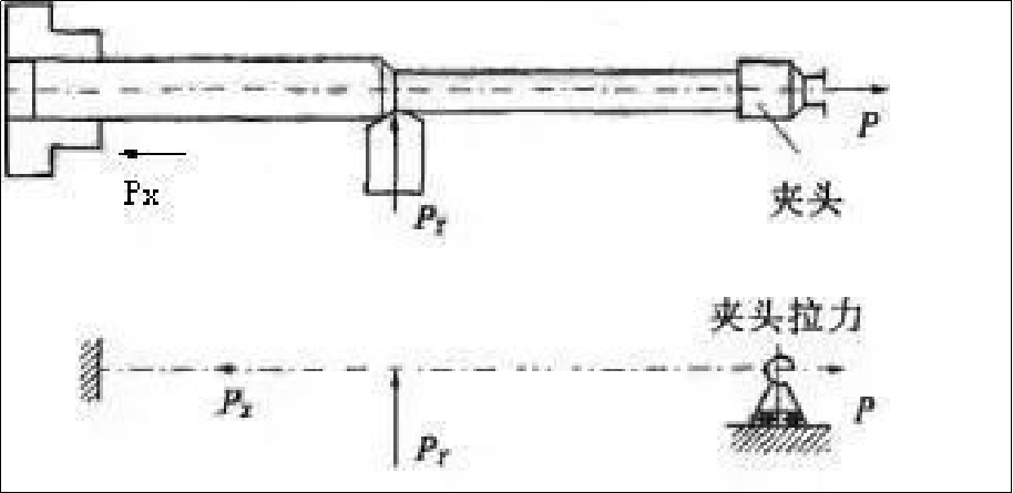
Figure 4 Axial clamping and stress conditions
The slender sleeve is subjected to constant axial tension during the turning process. This eliminates the problem of the axial cutting force bending the shaft. The axial force reduces the bending deformation caused by the radial cutting forces. It also compensates the axial lengthening due to the cutting heat. precision.
3) Reverse cutting the shaft to turn it
As shown in Figure 5, the reverse cutting method is when the tool is fed through the spindle to the tailstock during the process of turning the thin shaft.
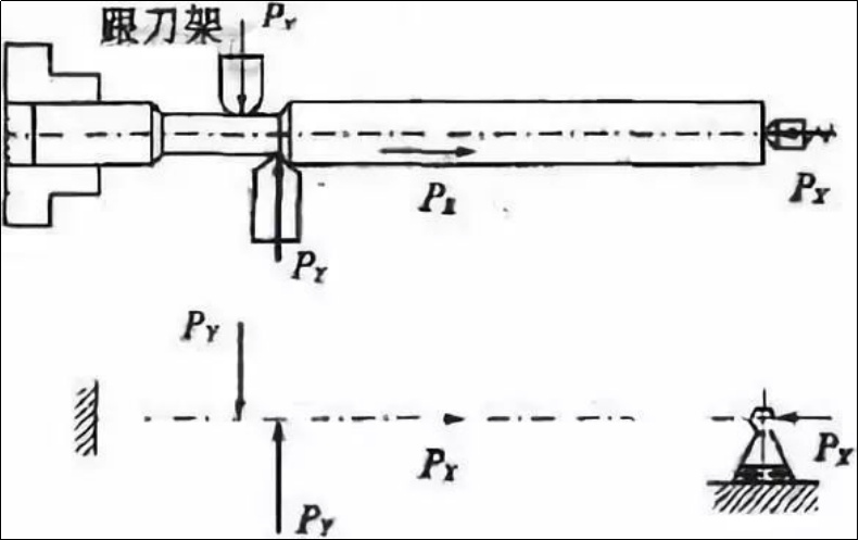
Figure 5 Analysis of Machining Forces and Machining by Reverse Cutting Method
The axial force that is generated during the processing will tension the shaft, preventing the bending deformation. The elastic tailstock can also compensate for the thermal elongation and compression deformation caused by the workpiece as it moves from the tool onto the tailstock. This prevents the deformation.
As shown in Figure 6, the middle slide plate is modified by adding the rear tool holder and turning both the front and rear tools simultaneously.
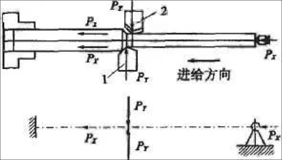
Figure 6 Force analysis and double-knife machining
The front tool is installed upright, while the rear tool is mounted in reverse. The cutting forces generated by the two tools cancel out each other during turning. The workpiece is not deformed or vibrated, and processing precision is very high. This is ideal for mass production.
4) Magnetic cutting technique for turning the thin shaft
The principle behind magnetic cutting is similar to reverse cutting. The magnetic force is used to stretch the shaft, reducing the deformation during the processing.
(3) Limit the amount of cutting
The amount of heat generated by the cutting process will determine the appropriateness of the cut amount. The deformation that is caused by rotating the thin shaft will also be different.
1) Depth of Cut (t)
According to the assumption that the rigidity is determined by the process system, as the depth of cut increases, so does the cutting force, and the heat generated when turning. This causes the stress and thermal distortion of the thin shaft to increase. When turning thin shafts, it is important to minimize the cutting depth.
2) Feeding amount (f).
Increased feed rate increases cutting force and thickness. The cutting force increases, but not proportionally. As a result, the force deformation coefficient for the thin shaft is reduced. In terms of increasing cutting efficiency, it is better to increase the feed rate than to increase the cutting depth.
3) Cutting speed (v).
It is advantageous to increase the cutting speed in order to reduce the force. As the cutting speed increases the temperature of the cutting tool, friction between the tool, the workpiece, and the shaft will decrease. If the cutting speeds are too high, then the shaft can easily bend due to centrifugal forces. This will ruin the stability of the process. The cutting speed of workpieces that are relatively large in length and diameter should be reduced.
(4) Select a reasonable angle for the tool
To reduce the bending deformation that is caused by turning a thin shaft, the cutting force during turning must be as low as possible. The rake, leading and edge inclination angles have the most influence on cutting force among the geometric angles of the tools.
1) Front angle (g)
The size of the rake (g) angle directly impacts the cutting force, temperature and power. The cutting force can be reduced significantly by increasing the rake angles. This reduces the plastic deformation and can also reduce the amount of metal being cut. In order to reduce the cutting forces, increasing the rake angles can be done. The rake angles are generally between 13deg and 17deg.
2) Leading angle (kr)
The main deflection (kr), which is the largest angle, affects the proportionality and size of all three components of cutting force. The radial force is reduced as the entering angle increases, while the tangential force increases between 60deg and 90deg. The proportional relationship between the three components of cutting force is better in the range 60deg75deg. A leading angle greater 60deg is usually used when turning thin shafts.
3) Blade inclination
The inclination of the blade (ls), affects the flow of chips and the strength of tool tip, as well as the proportional relationship between the three turned components of cutting during the turning process. The radial force of cutting decreases as the inclination increases. However, the axial and tangential forces increase. The proportional relationship between the three components of cutting force is reasonable when the blade inclination is within the range of -10deg+10deg. In order to get the chips to flow towards the surface of the shaft when turning a thin shaft, it is common to use a positive edge angle between 0deg and +10deg.
It is difficult to meet the quality standards of the slender shaft due to its poor rigidity. The processing quality of the slender shaft can be assured by adopting advanced processing methods and clamping techniques, as well as choosing the right tool angles and parameters.
Anebon’s mission is to recognize excellent manufacturing imperfections and provide the best service to our domestic and overseas customers completely for 2022 Top quality Stainless Aluminium High Precision CNC Turning Milling Machine Part part for Aerospace in order to expand our market internationally, Anebon mainly supply our overseas customers with top quality machines, milled pieces and CNC turning services.
China wholesale China Machinery Parts and CNC Machining Service, Anebon keeps the spirit of “innovation and cohesion, teamwork, sharing, trail, practical advancement”. If you give us a chance, we’ll show our potential. With your support, Anebon believe that we will be able to build a bright future for you and your family.
Post time: Aug-28-2023