
What do you know about the dimensioning details in mechanical design that need to be paid attention to?
Dimensions of the overall product:
They are the dimensions which define the overall shape and size of an object. These dimensions are usually represented as numerical values in the rectangular boxes indicating height, width and length.
Tolerances:
Tolerances are the allowed variations in dimensions that ensure proper fit, function, and assembly. Tolerances are defined by a combination plus and minus symbols along with numerical values. A hole with a 10mm diameter +- 0.05mm, for example, means that the diameter range is between 9.95mm to 10.05mm.
Geometric Dimensions & Tolerances
GD&T allows you to control and define the geometry of components and assembly features. The system includes control frames and symbols to specify such features as flatness (or concentricity), perpendicularity (or parallelism), etc. This gives more information on the shape and direction of features than basic dimensional measurements.
Surface Finish
Surface finish is used to specify the desired texture or smoothness of the surface. The surface finish is expressed using symbols like Ra (arithmetical mean), Rz(maximum height profile), and specific roughness values.
Threaded Features
To dimension threaded items, such as bolts or screws, you must specify the thread size, pitch and thread series. You can also include any other details, like thread length, chamfers or thread length.
Assembly Relationships & Clearances
Dimensioning details are also important when designing mechanical assemblies to consider the relationship between components, as well as the clearances needed for proper function. It is important to specify mating surfaces, alignments, gaps and any tolerances required for functionality.
Dimensioning methods for common structures
Dimensioning methods for common holes (blind holes, threaded holes, countersunk holes, countersunk holes); dimensioning methods for chamfers.
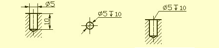
❖ Blind hole
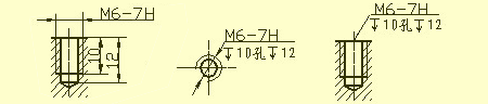
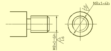
❖ Threaded hole
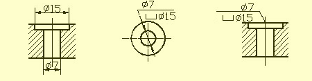
❖ Counterbore
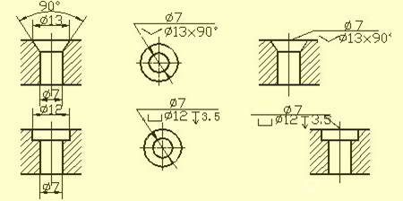
❖ Countersinking hole
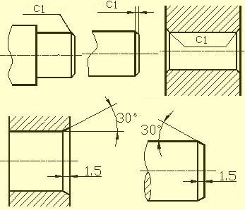
❖ Chamfer
Machined structures on the part
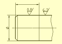
❖ Undercut groove and grinding wheel overtravel groove
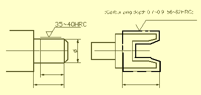
To facilitate the removal of the tool from the part and to ensure that the surfaces of parts in contact are the same during assembly, a pre-processed undercut groove, or a grinding wheels overtravel groove, should be applied at the stage of the surface being processed.
In general, the size of the undercut can be indicated as “groove depth x diameter”, or “groove depth x groove width”. The overtravel groove of the grinding wheel when grinding the end face or the outer circular.
❖Drilling structure
Blind holes drilled by a drill have a 120deg angle at the bottom. The depth of the cylinder part is the drilling depth, excluding the pit. The transition between the stepped hole and the 120deg cone is marked by a cone with a drawing method, as well as dimensionaling.
To ensure accurate drilling, and to avoid drill bit breaking, it is important that the drill bit’s axis be perpendicular as possible to the face of the end being drilled. The image below shows how to correctly structure the three drilling ends faces.
❖Bosses and dimples
In general, the surfaces that come into contact with other parts or parts need to be treated. Bosses and pits on castings are commonly designed to reduce processing area while ensuring good contact between surfaces. Support surface bosses and support surface pits are bolted; to reduce the processing surface, a groove is created.
Common Part Structures
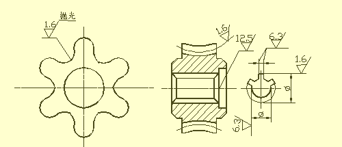
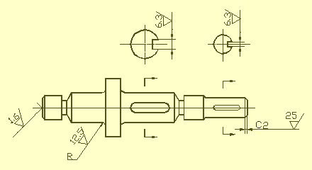
❖Shaft sleeve parts
Shafts, bushings, and other parts are examples of such parts. As long as the basic view and cross-sections are shown, it is possible to express its local structure and main features. The axis for projection is usually placed horizontally to make it easier to view the drawing. The axis should be placed on a vertical side line.
The axis of the bushing is used to measure the radial dimensions. This is used to determine F14, and F11 (see Section A-A), for example. The figure is drawn. The design requirements are unified with the process benchmark. For example, when processing shaft parts on a lathe you can use thimbles to push the shaft center hole. In the length direction, the important end face or contact surface (shoulder), or machined surface can be used as a benchmark.
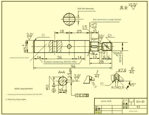
The figure shows that the shoulder on the right with surface roughness Ra6.3, is the main reference for the dimensions in the direction of length. Sizes such as 13, 14, 1.5, and 26.5 can be drawn from it. The auxiliary base marks the shaft’s total length 96.
❖Disk cover parts
This type of part is generally a flat disk. It includes end covers, valve cover, gears, and other components. The main structure of these parts is a rotating body with various flanges and round holes evenly distributed. Local structures, such as ribs. As a general rule, when selecting views you should choose the section view along the axis or plane of symmetry as your main view. You can also add other views to the drawing (such as a left view, a right view, or a top view) in order to show the uniformity of the structure and the shape. In the figure it is shown that a left-side view has been added to show the square flange, with its rounded corners and evenly distributed four through holes.
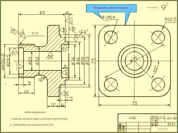
When making measurements of disk cover components the axis of travel across the shaft’s hole generally chosen as the radial dimension axis and the most important edge is typically chosen as the primary dimension datum in the direction of length.
❖ Parts for the Fork
They typically comprise the connecting rods and shift forks supports, and various other components. Due to their different processing positions, the work location and the shape of the part are considered when choosing the view that will be used as the primary. The selection of alternative views usually will require at least two basic perspectives as well as appropriate sections views, partial views, and other expression techniques are used to show how the structure is local to the piece. The selection of views shown in the parts of the pedal seat diagram is simple and easy to understand. In order to express the size of the rib and bearing the right view is not needed, but for the rib that is T-shaped it is better to use the cross-section. suitable.
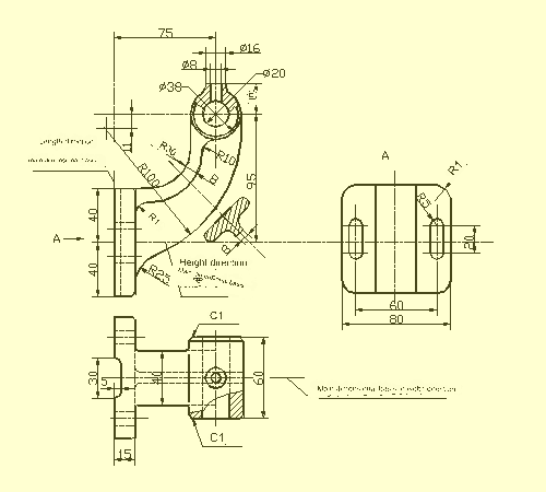
When measuring the dimensions of fork-type components the base of the part as well as the symmetry plan of the piece is often used as a dimensions’ reference point. Check out the diagram for methods of determining the dimensions.
❖ Parts of the box
In general, the form and the structure of part is more complicated than the other three kinds of parts. Additionally, the positions of processing change. They typically comprise valve bodies, pump bodies reducer boxes, and various other components. When selecting a view for the main view, the primary concerns are location of the work area and the characteristics of the shape. If you are choosing other views, appropriate auxiliary views such sections or partial views, sections and oblique views must be selected based on the situation. They should clearly convey the external and internal structure of the piece.
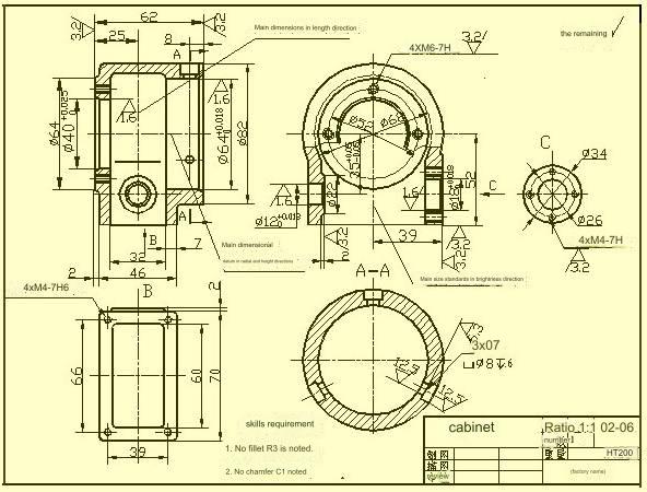
In terms of dimensioning, the axis that is required to be used by design key mounting surface and the Contact area (or process surface) as well as the symmetry plan (width length) of the main structure of the box, etc. are often used as the dimensions of the reference. When it comes to the areas of the box which require cutting the dimensions must be marked as precisely as is possible in order to ease handling and inspect.
Surface roughness
❖ Concept of roughness of the surface
The microscopically shaped geometric characteristics consisting of peaks and valleys that have tiny gaps across the surface are known as roughness of the surface. This is caused by the scratches left behind by tools on the surfaces in the course of manufacturing parts, and the deformation caused by the plastic of the metal’s surface in the process of cutting and cutting and splitting.
The roughness of surfaces is also a scientific indicator to evaluate the quality of the parts’ surface. It affects the properties of the parts, their matching accuracy, wear resistance corrosion resistance, sealing appearance and appearance. of the component.
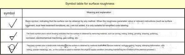
❖ Surface roughness codes symbols, markings and marks
The GB/T 131-393 document specifies the surface roughness code as well as its notation technique. The symbols that indicate the roughness of the surface elements on the drawing are listed on the following table.
❖ Principal evaluation parameters of roughness of surfaces
The parameters used to evaluate roughness of the part’s surface are:
1.) Arithmetic mean deviation of contour (Ra)
The arithmetic mean of Absolute value of the contour offset in the length. The values of Ra as well as the length of sampling is shown in this table.
2.) Maximum maximum height of profile (Rz)
The sampling duration is it is the gap between the contour peak’s top and bottom lines.
Take note: Ra parameter is preferred when making use of.
❖ The requirements for labeling surface roughness
1.) An example of code labeling to indicate roughness of the surface.
The surface roughness height values Ra, Rz, and Ry are labeled by numerical values in the code, unless it is possible to leave out the parameter code Ra is not required in lieu of the appropriate value for the parameter Rz or Ry must be identified prior to any parameter values. Check out Table for an example of how to label.
2.) Technique of marking symbols and numbers on rough surfaces
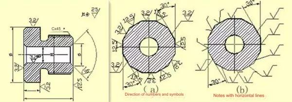
❖ How do I mark roughness of surface symbols on drawings
1.) The roughness of the surface (symbol) should be placed with the contour lines visible or dimension lines, or on their extension lines. The point of the symbol should point from the exterior of the material and towards the surface.
2.) 2. The particular direction for symbols and numbers in the roughness code on surfaces is to be marked in accordance with the regulations.
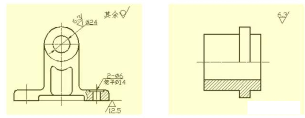
A good example of marking roughness of surface
The same drawing is used for every surface is usually marked using only the one-generation (symbol) and closest to the dimension line. If the area isn’t large enough or is difficult to mark, it is possible to draw the line. When all surfaces on an item meet the same requirements for surface roughness the markings can be made equally in the upper right part of your drawing. When the majority of the surfaces of a piece share the same surface roughness specifications, the most frequently employed code (symbol) is at simultaneously, write this in the upper left area of your drawing. Also, include”rest” “rest”. The dimensions of all uniformly identified surfaces roughness symbol (symbols) and explanation text must be 1.4 times the height of the markings on the drawing.
The roughness of the surface (symbol) on the continuously curved surface of the component, the surface of elements that are repeated (such as teeth, holes grooves, holes or grooves.) as well as the discontinuous surface joined by thin solid lines are only observed only once.
If there are multiple specifications for surface roughness for the exact same area the thin solid line should be drawn to mark the division line and the appropriate roughness and dimensions should be recorded.
If it is determined that the tooth (tooth) shape isn’t traced on the surface of threads, gears or other gears. The roughness of the surface code (symbol) can be seen in the illustration.
The roughness codes for the work surface of the central hole, the side of the keyway fillets and chamfers could simplify the process of labeling.
If the cnc milled parts are to be treated with heat or partially coated (coated) the entire area should be marked with thick lines of dotted lines, and the dimensions that correspond to it should be clearly marked. The specifications can appear on the line horizontally along the long edge of the surface roughness symbol.
Basic tolerances and standard deviations
To facilitate production allow interoperability of cnc machined components and meet different requirements of use, the standard national “Limits and Fits” stipulates that the tolerance zone comprises of two components that are the standard tolerance and the basic deviation. The standard tolerance is what determines how large the zone of tolerance and the basic deviation decides the area of the tolerance zone.
1.) Standard Tolerance (IT)
The quality of the Standard tolerance will be determined by size of the base and the class. A tolerance class is a measure that defines the accuracy of measurements. It is divided in 20 levels, specifically IT01, IT0and IT1. ,…, IT18. The accuracy of the dimensional measurements decreases as you move from IT01 until IT18. For more specific standards for standard tolerances check out the relevant standards.
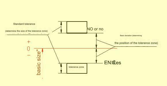
Basic Deviation
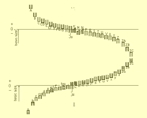
Basic deviation is the upper or lower deviation relative to zero in the standard limits, and generally refers to deviation close to zero. The basic deviation is lower when the tolerance zone is higher than the zero line; otherwise it is upper. The 28 basic deviations are written in Latin letters with uppercase for the holes and lowercase to represent the shafts.
On the diagram of basic deviations, it is clear that the hole basic deviation AH and shaft basic deviation kzc represent the lower deviation. The hole basic deviation KZC represents the upper deviation. The upper and lower deviations for the hole and shaft are respectively +IT/2 and –IT/2. The basic deviation diagram does not show the size of tolerance, but only the location of it. The standard tolerance is the opposite end of an opening at the end of a tolerance zone.
According to the definition for dimensional tolerances, the calculation formula for the basic deviation and standard is:
EI = ES + IT
ei=es+IT or es=ei+IT
The tolerance zone code for the hole and shaft is made up of two codes: the basic deviation code, and the tolerance zone grade.
Cooperate
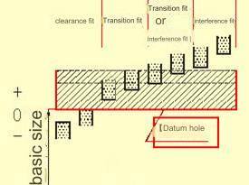
Fit is the relationship between the tolerance zone of the holes and shafts which have the same basic dimension and are combined together. The fit between the shaft and hole can be tight or loose depending on the application requirements. Therefore, the national standard specifies the different types of fit:
1) Clearance fit
The hole and shaft should fit together with a minimum clearance of zero. The hole tolerance zone is higher than the shaft tolerance zone.
2) The transitional cooperation
There may be gaps between the shaft and hole when they are assembled. The hole’s tolerance zone overlaps that of the shaft.
3) Interference fit
When assembling the shaft and hole, there is interference (including minimal interference equal to zero). The tolerance zone for the shaft is lower than the tolerance zone for the hole.
❖ Benchmark system
In the manufacturing of cnc machined parts, a part is selected as a datum and its deviation is known. The datum system is a way to obtain different types of fit with different properties, by changing the deviation of another part that is not a datum. National standards specify two benchmark systems based on the actual production requirements.
1) The basic hole system is shown below.
Basic hole system (also called basic hole system) is a system where the tolerance zones of a hole that has a certain deviation from the standard and the tolerance zones of a shaft which have different deviations from the standard form various fits. Below is a description of the basic hole system. Refer to the diagram below.
①Basic hole system
2) The basic shaft system is shown below.
Basic shaft system (BSS) – This is a system where the tolerance zones of a shaft and a hole, each with a different basic deviation, form various fits. Below is a description of the basic axis system. The datum axis is the axis in the basic axis. Its basic deviation code (h) is h and its upper deviation is 0.
②Basic shaft system
❖ Code of cooperation
Fit code is composed of the tolerance zones code for the hole and shaft. It’s written in fractional form. The tolerance zone code for the hole is in the numerator, while the tolerance code for the shaft is in the denominator. A basic axis is any combination that contains h as the numerator.
❖ Marking tolerances and fit on drawings
1) Use the combined marking method to mark tolerances and fit on the assembly drawing.
2) Two different types of marking are used on machining parts drawings.
Geometric tolerance
There are geometrical errors and errors in mutual position after the parts have been processed. The cylinder may have a qualified size but be larger at one end than the other, or thicker in the middle, while thinner at either end. It may also not be round in cross-section, which is a shape error. After processing, the axes of each segment can be different. This is a positional error. Shape tolerance is the variation that can be made between the ideal and the actual shape. Position tolerance is the variation that can be made between the actual and ideal positions. Both are known as geometric tolerances.
Bullets with Geometric Tolerance
❖ Tolerance codes for shapes and positions
The national standard GB/T1182-1996 specifies the use codes to indicate shape and position tolerances. When the geometric tolerance is not able to be marked by a code in actual production, the text description can be used.
Geometric tolerance codes consist of: geometric tolerance frames, guide lines, geometric tolerance values, and other related symbols. The font size in the frame has the same height as the font.
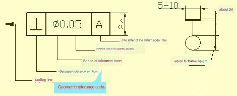
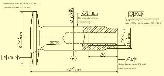
❖ Geometric tolerance marking
The text near the geometric tolerance shown in the figure can be added to explain the concept to the reader. It does not have to be included in the drawing.
Anebon is proud from the higher client fulfillment and wide acceptance due to Anebon’s persistent pursuit of high quality both on product and service for CE Certificate Customized High Quality Computer Components CNC Turned Parts Milling Metal, Anebon has been keeping chasing WIN-WIN scenario with our consumers. Anebon warmly welcome clientele from all around the entire world coming in excess of for a visit and setting up long lasting romantic relationship.
CE Certificate China cnc machined aluminium components, CNC Turned Parts and cnc lathe parts. All the employees in factory, store, and office of Anebon are struggling for one common goal to provide better quality and service. Real business is to get win-win situation. We would like to provide more support for customers. Welcome all nice buyers to communicate details of our products and solutions with us!
If you want to know more or need a quote, please contact info@anebon.com
Post time: Nov-29-2023