
How much do you know about mechanical design?
It involves designing, analyzing and optimizing various mechanical elements to meet desired specifications and requirements. It involves designing, analyzing, and optimizing various mechanical elements to meet desired specifications and requirements.Mechanical design can encompass a wide range of areas, including product design, machine design, equipment design, and structural design. Understanding and applying basic engineering principles such as thermodynamics and materials science is required.
The mechanical design is a part of the design, manufacture, use and maintenance processes. Negligence in design will always reflect on these aspects. It is not difficult to determine whether a project will be successful or fail. Manufacturing has a great influence on the design process, so good design is not separate from manufacturing. Understanding manufacturing will help you improve your design skills.
Mechanical design is primarily concerned with creating reliable, cost-effective, and efficient solutions. Designers often use computer-aided design (CAD) software and tools to develop detailed models, conduct simulations, and evaluate performance before manufacturing.Throughout the design process, mechanical designers consider factors such as safety, reliability, manufacturability, ergonomics, aesthetics, and environmental impact. To ensure the seamless integration and functionality, they work with other engineering disciplines such as civil, industrial, and electrical engineers.
There are not many people I’ve seen who can immediately assemble and process the drawings after they have been put into production. During the drawing review process and the subsequent process, it is not uncommon to find many problems. This includes drawings created by so-called senior engineers or chief engineers. This is the result after repeated discussions and many meetings. This is due to a number of factors. On the one hand there is standardization in the drawing, and the level of viewer. But the lack of understanding by the designer of the manufacturing process on the other hand is the main cause.
How do you determine how much you know about manufacturing?
Grab a sketch of what you’ve designed. What is the whole manufacturing process? It is impossible to do casting, forging and turning. Milling, planing and grinding are also not possible. Anyone who has worked for several years in a machine shop knows this. To fully understand the process, it must be broken into smaller steps. The part structure may cause an accident during heat treatment. It is important to know how to optimize it and how to cut the material. Virtualization is used to simulate the process, which includes the number of knives, rotation speed, tool feed amount, even the direction in which iron chips are thrown, the order of using the knives, and the operation of the lathe. We can say that we now have a stronger foundation.
The principles for selecting materials for mechanical parts
should consider three aspects of requirements
1. Usage requirements (primary consideration):
1) The working conditions of the parts (vibration, impact, high temperature, low temperature, high speed, and high load should all be treated with caution); 2) Limitations on the size and quality of the parts; 3) The importance of the parts. (Relative importance to the reliability of the entire machine)
2. Process requirements:
1) Blank manufacturing (casting, forging, plate cutting, rod cutting);
2) Mechanical processing;
3) Heat treatment;
4) Surface treatment
3. Economic requirements:
1) Material price (comparison between the blank cost and processing cost of ordinary round steel and cold-drawn profiles, precision casting, and precision forging);
2) Processing batch size and processing costs;
3) Utilization rate of materials; (such as the specifications of plates, bars, and profiles, use them reasonably)
4) Substitution (try using cheap materials to replace expensive rare materials such as ductile ink to replace copper sleeves in certain wear-resistant parts or oil-containing bearings in place of some turning sleeves and nylon in the case of low speed loads) Replace steel gears with copper worm gears etc.
Also, consider the availability of local materials
1. Basic requirements for mechanical design
a) Pay attention to coordination and balance regarding the functional requirements of the machine! Prevent the barrel effect from occurring
b) Machine economy requirements: Design economy, get it into production quickly, recover consumption during development, and even design-manufacture at the same time for economy. This will give you the best price/performance ratio (products start in small batches).
2. Basic requirements for mechanical parts design
a) Work normally and reliably within the scheduled working period to ensure the various functions of the machine;
b) Minimize the production and manufacturing costs of parts;
c) Use as many common standard parts in the market as possible;
d) When designing products that could be serialized, consider the versatility of parts. The structure of those that are not universal should be similar to the maximum extent possible in order to reduce the complexity of the manufacturing process, and the time required for fixture and tooling designs.
View selection of typical parts in mechanical drawing
The structural shape of a part is the main factor in determining the expression scheme for the part view. Parts with similar shapes share common characteristics.
Generally, machine parts can be divided into categories based on their shape, such as bushings and wheel discs. Here are their characteristics expressed in different ways:
(1) Select shaft and sleeve components
The axis of the shafts or sleeve part is horizontally positioned according to its processing position. In general, a basic and cross-sectional views, as well as a partial enlarged version, are all that is needed.
(2) Browse our selection of wheel and disk parts
In the main view, the axis is also horizontally positioned according to the position of the processing. This requires two basic views.
(3) Fork and Rod Parts
Forks and rods, for example, are frequently curved and tilted. The view that best represents their shape characteristics will be used as the main image. Two or more basic images may also be required.
(4) Box parts selection
Box-type components are more complex. The main view placement must correspond to the working position of the part on the machine. In general, at least three basic views are needed.
There are often several different expression schemes for the same part. Each has its own benefits and drawbacks and should be compared and analysed in detail.
When selecting views, it is important that each view has a distinct focus. The view selected should be complete and clear, and easily readable.
Shaft and sleeve parts
The main purpose of shaft and sleeve components is to transmit power, or support other parts such as shafts.
(1) The structural characteristics and the processing methods for shaft and sleeve components
The main components of these rotating bodies are cylinders, cones and other rotating body of various sizes. The majority of shaft and sleeve components are processed using lathes or grinders. These auto spare parts are often designed, processed or assembled with structures like chamfers and threads. They may also have undercuts, pinholes, keyways or flat surfaces.
(2) View selection
The shaft and sleeve part is represented with a frontal view, the axis horizontally placed. This is followed by an appropriate number or cross-sectional and enlarged partial views. The horizontal positioning of the main view is consistent not only with the feature principle for part view selection but also with its processing position and working position.
Partial sections can be used to represent structures such as holes and pits in the shaft. As shown in Figure 3- 7, the keyways, holes and structural planes, among other structures, need to be represented as separate cross-sectional view.
Solid shafts do not need to be cut, but sleeve components must be to show their internal structure. Full section views can be used if the external form is simple; half section views can be used if it is complex.
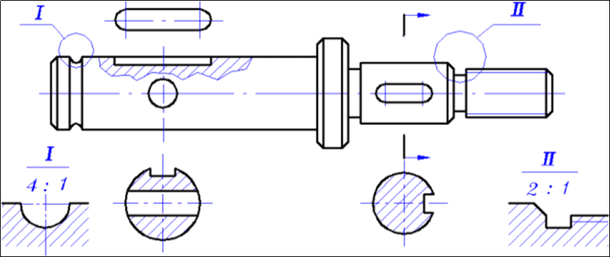
Figure 3-7 Axis expression method
Pan and cover parts
Included in the disc and cover parts are end covers, flanges (handwheels), pulleys, and other flat disc-shaped components. Wheels are used to transmit power and covers serve mainly as support, axial position, and sealing.
1. Structural features
The main body of the disk or cover part is usually a coaxial rotating body. Some have main bodies that are square, rectangular, or another shape, with larger radial and smaller axial measurements. As shown in Figures 3-8, parts often feature structures like shaft holes, holes along the circumference of the part, ribs or grooves, and teeth.
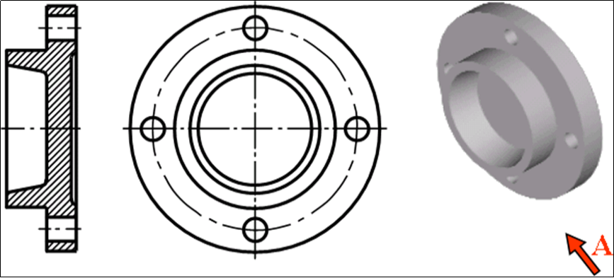
Figure 3-8 Expression method of plate/cover parts
(2) View selection
Usually, disk and cover parts can be expressed in two basic perspectives. The main view is the full cross-section through the axis. The axis should be horizontally positioned to match its processing position. The main view of some parts, which are not processed primarily by lathes can be determined based on their shape and position.
A basic view of the disk and the cover is a way to express the distribution of holes, grooves and other structures around the disk or cover. When the view is symmetrical, a half-section view may be used.
Forks and frame parts
The frame and fork parts include the connecting rods, brackets etc. For various purposes. Shift forks and tie rods play an important role in machine control systems. Brackets serve a similar purpose. These blanks are usually cast or forged.
(1) Structural features
The majority of forks and frames are made up of three parts: the working part, the installation part, and the connecting part. Working part refers to the part of the fork or frame that has an effect on other parts. The mounting holes on the rectangular bottom plate of bracket are used to position and connect the bracket. The bracket’s support plate connects the working and installation parts. When designing bracket parts, it is common to construct the working and installation parts of the part first, then add the connecting part.
(2) View selection
Forks and frames are often shaped in complex ways, with curved or tilted structures. The parts are subjected to many different processing steps, and the working positions of these parts are not fixed. In general, the view which best reflects the shape characteristics of the object is chosen as the main image. Other views, partial view, cross-sections, and other expression methods, in addition to the main views, are selected based on its structural characteristics. As shown in Figure 3-9.
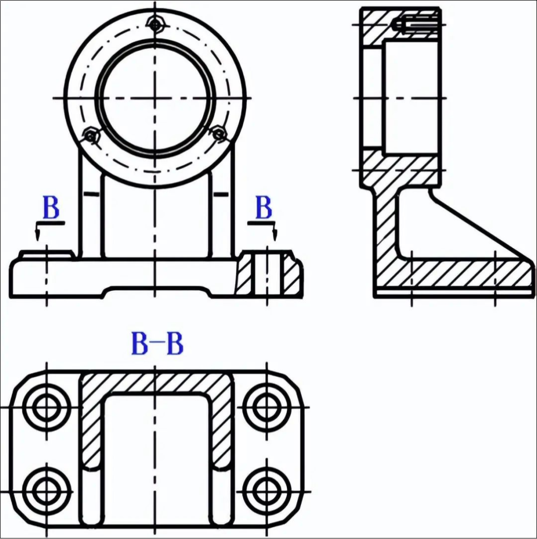
Figure 3-9 Expression method of bracket parts
Box Parts
Box parts include pump bodies, valve bodies, machine bases, reduction boxes, etc. Castings are used to make box parts, which are the main components of machines and components. Supports, seals, and positions are usually used.
1. Structural features
The box structure varies according to the functional requirements. However, most are hollow shells that have large inner cavities. The inner cavity shape is determined by the motion trajectory and shape of the machined components contained within the box. The bearing hole is the part that supports the moving parts of the box. The end face of the hole has local functional structures, such as a plane to install the end cover or screw holes.
(2) View selection
The processing positions for each of the processes are different. Box parts have complex structural features and complicated processing procedures. The main view is usually selected based on the working position of the box and its shape characteristics. To express the complicated internal and external shapes, it is necessary to have a sufficient amount of cross-sectional drawings and outline drawings. Particular views and partial enlargements can be used to supplement detailed structures.
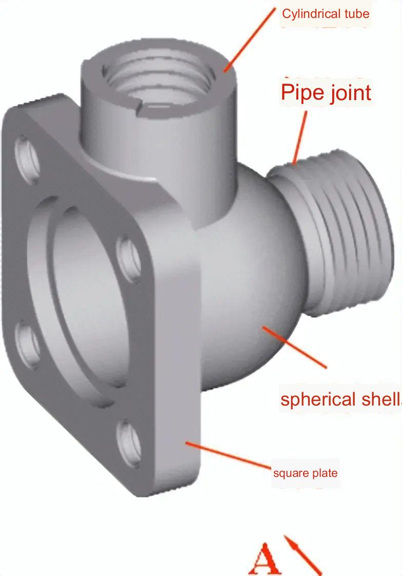
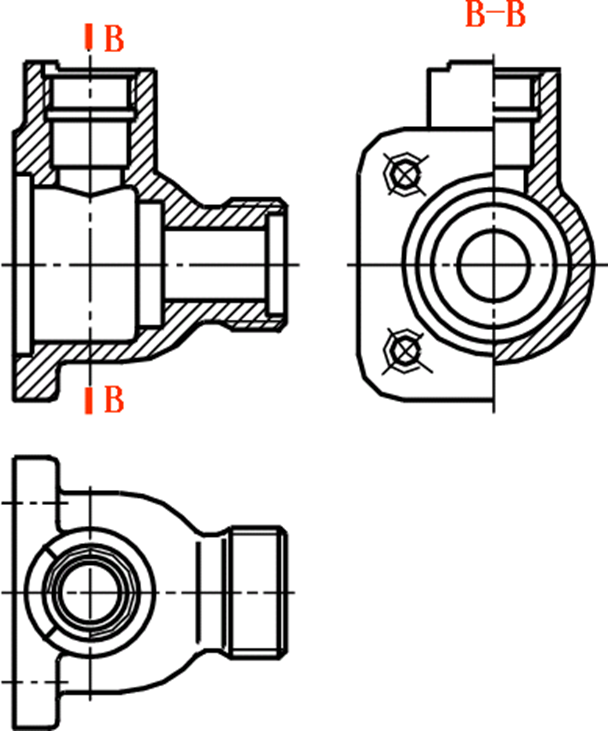
Figure 3-10 Expression method of valve body parts
Figure 3-10 shows the valve body. It consists of four parts: a spherical tube, a squareplate, and a pipe connection. The inner holes of the spherical and cylinder parts are connected by the intersection between the two. The front view of the valve is arranged according to its current working condition. The front view is fully sectioned to show the internal shape of the valve, its relative position, etc.
Choose the half-section view left to show the appearance of the main body of the valve, the shape and size of the square plate on the left side of the valve and the inner hole structure. Select a top-view to show the overall shape and fan-shaped top structure of the valve.
Anebon have the most advanced production equipment, experienced and qualified engineers and workers, recognized quality control systems and a friendly professional sales team pre/after-sales support for China wholesale OEM Plastic ABS/PA/POM CNC Lathe CNC Milling 4 Axis/5 Axis CNC machining parts, CNC turning parts. Currently, Anebon is seeking ahead to even bigger cooperation with abroad customers according to mutual gains. Please experience free of charge to get in touch with us for more specifics.
2022 High quality China CNC and Machining, With a team of experienced and knowledgeable personnel, Anebon’s market covers South America, the USA, the Mid East, and North Africa. Many customers have become friends of Anebon after good cooperation with Anebon. If you have the requirement for any of our products, remember to contact us now. Anebon will look forward to hearing from you soon.
Post time: Sep-12-2023