
How much do you know about the whole process of mechanical assembly?
Mechanical assembly is the process of assembling various parts to form a functioning mechanical system or product. This includes reading and understanding engineering drawings, choosing and using appropriate tools and equipment to fit and align parts, attaching components with various techniques (such a bolting, adhesives, or welding), and performing quality tests to ensure proper functionality. Assembly processes can be tailored to the needs and complexity of each product.
Homework preparation
(1) Operation Data: includes general assembly drawings (GA), component assembly drawings (CA), parts drawings (PD), material BOM lists etc. The completeness, neatness, and integrity of all process information records and drawings must be maintained until the end of the construction project.
(2) Workplace: The place where the parts are placed and components assembled must be specified. It is important to plan the place where you will assemble and place your machine. All work areas must be neat, standardised and ordered until the project is completed.
(3) Assembly materials. The assembly materials must be ready before the operation. The order of the operations can be altered if certain non-deterministic material is not available. A material expediting form must then be completed and sent to the purchasing department.
(4) Before assembly, it is important to understand the structure, assembly process and technology requirements of equipment.
Basic specification
(1) The mechanical assembly must be performed in strict compliance with the assembly drawings, process requirements and instructions provided by the design team. It is prohibited to change the content of work without permission, or to alter parts in an abnormal way.
(2) The assembled parts should be parts that passed inspection and approval by the quality assurance department. Report any non-qualified parts found during the assembly.
(3) The assembly area must be free from dust and other pollutants. The parts should be kept in a dust-free, dry place and protected with pads.
(4) Parts must be assembled without being bumped, cut or damaged on the surface. They may, however, be bent, twisted or deformed in a significant way. The mating surfaces must also not be damaged.
(5) When assembling parts that are relatively mobile, it is advisable to add lubricating grease (oil) between the surfaces of contact.
(6) The dimensions of the matching parts should be exact.
(7) Parts and tools must be placed in a special way during assembly. Parts and tools should not be placed directly on or on top of the machine. In the event that protective mats or carpets are required, they should be placed in the area of placement.
In principle, it is forbidden to step on the machine during assembly. In the event that it is necessary to walk on the machine, carpets or mats should be placed on top. Stepping on important parts or non-metallic components with low strength is strictly forbidden.
Join method
(1) Bolt connection
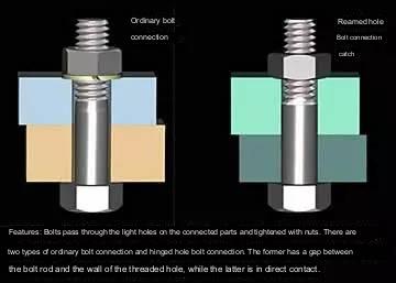
A. Use only one washer per nut when tightening bolts. The nail heads must be embedded into the machine parts after the countersunk screw is tightened.
B. In general threaded connections need anti-loose washers. The method for tightening multiple symmetrical bolts is to tighten them gradually and in a symmetrical manner. Strip connectors are also tightened gradually and symmetrically from the middle outwards.
C. When the screws are not required to be disassembled during the fastening or maintenance of the moving device, they should be coated in thread glue prior to assembly.
D. A torque wrench is used to tighten fasteners that have specified torque requirements. Bolts without a specified torque should be tightened according to the “Appendix” regulations.
(2) Pin connection
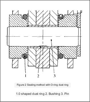
A. In general, the end face of the pin should be slightly higher than surface of the milling components. The big end of the screw-tail tapered pin should be sunk into the hole after it has been installed in the part.
B. The cotter pin’s tails must be 60deg to 90deg apart after it has been loaded into the appropriate parts.
(3) Key connection
A. There should not be any gap between the mating surfaces of the flat and fixed keys.
B. When the moving parts of the key or spline are moved in the axial direction after assembly, there should be no unevenness.
C. The hook key and wedge keys should be assembled so that their contact area does not fall below 70% of the total working area. Non-contact parts must not be grouped together, nor should the exposed part be more than 10%-15% the length.
(4) Riveting

A. Materials and specifications for riveting must be in accordance with the design requirements. The processing of the holes of the rivets should also meet relevant standards.
B. The surface of riveted aluminum components must not be damaged or deformed when riveting.
C. There should be no looseness in the riveted part, unless there are specific requirements. The head of rivets must be in contact with the riveted part and smooth and round.
(5) Expansion sleeve connection
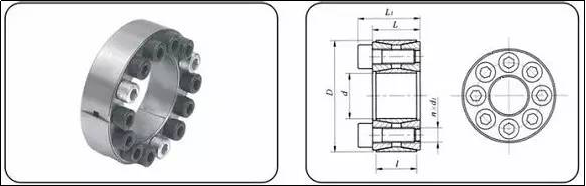
Expansion sleeve assembly: Apply lubricating grease to the expansion sleeve, put the expansion sleeve into the assembled hub hole, insert the installation shaft, adjust the assembly position, and then tighten the bolts. The order of tightening is bounded by the slit, and the left and right are crossed and symmetrically tightened successively to ensure that the rated torque value is reached.
(6) Tight connection
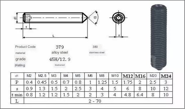
Set screws with conical ends should have a 90-degree tapered end. The hole should be 90 degrees.
Installation of linear guides
(1) The installation surface of the guide rail must be flat and free of dirt.
(2) If the guide rail has a reference edge, the rail should be installed near the edge. If there is not a reference edge, then the sliding direction should match the design requirements. Check the slide direction after tightening the screws on the guide rail. If not, it will need to be adjusted.
(3) If the slide is driven by transmission belts, then the belts must be fixed and tensioned before the belt can be pulled in an oblique direction. Otherwise, the pulley should be adjusted to ensure that the belt’s driving direction is parallel with the guide rail.
Assembly of sprocket chains
(1) The sprocket must be designed to cooperate with the shaft.
(2) The gear teeth of both the driving and driven sprockets should have the same geometric center plane, and their offsets must not exceed design requirements. It should be less than or equivalent to 2%0, if not specified by the design.
(3) The working side of the chain must be tightened when it meshes with a sprocket.
(4) The chain sag on the side that is not in use should be within the limits of the design. It should be adjusted if it isn’t specified in the design.
Gear assembly
(1) When the gear rim is 20mm or less, axial misalignment must not exceed 1mm. If the gear width is more than 20mm the misalignment cannot exceed 5%.
(1) JB180-60 “Bevel Gear transmission Tolerance”, JB162 and JB162 should specify the installation accuracy requirements for cylindrical gears and bevel gears.
According to technical requirements, the meshing surfaces of gears must be lubricated according to normal practice. The gearbox should be filled to the level line with lubricating oils.
(4) The noise level of the transmission at full load must not exceed 80dB.
Rack adjustment and connection
(1) Racks in different sections of the racks should all be set to the exact same height, using the same reference point.
(2) All racks’ wall panels should be aligned on the same vertical plane.
(3) The fixed connecting plates should then be installed between the sections after the racks have been adjusted to the required height and dimensions.
Assembly of pneumatic components
(1) The configuration of each set of pneumatic drive devices must be connected strictly in accordance with the pneumatic circuit diagram provided by the design department. The valve body, pipe joints, cylinders, etc. must be connected correctly.
(2) The inlet and outlet of the total air intake pressure reducing valve are connected in the direction of the arrow, and the water cup and oil cup of the air filter and lubricator must be installed vertically downward.
(3) Before piping, the cutting powder and dust in the pipe should be fully blown off.
(4) The pipe joint is threaded. If the pipe thread does not have thread glue, the raw material tape should be wrapped. The winding direction is clockwise when viewed from the front. The raw material tape must not be mixed into the valve. The raw material tape should not be mixed into the valve. When winding, one thread should be reserved.
(5) The layout of the trachea should be neat and beautiful, and try not to cross the arrangement. 90deg elbows should be used at the corners. When fixing the trachea, do not put extra stress on the joints, otherwise it will cause air leakage.
(6) When connecting the solenoid valve, pay attention to the function of each air port number on the valve: P: total air inlet; A: air outlet 1; B: air outlet 2; R (EA): exhaust corresponding to A; S (EB) : Exhaust corresponding to B.
(7) When the cylinder is assembled, the axis of the piston rod and the direction of load movement should be consistent.
(8) When using linear bearing guide, after the front end of the cylinder piston rod is connected to the load, there must not be any strange force during the entire stroke, otherwise the cylinder will be damaged.
(9) When using a throttle valve, you should pay attention to the type of the throttle valve. Generally speaking, it is distinguished by the large arrow marked on the valve body. The large arrow pointing to the thread end is used for the cylinder; the large arrow pointing to the pipe end is used for the solenoid valve. .
Assembly inspection work
(1) Every time the assembly of a component is completed, it must be checked according to the following items. If an assembly problem is found, it should be analyzed and dealt with in time.
A. The integrity of the assembly work, check the assembly drawings, and check whether there are missing parts.
B. For the accuracy of the installation position of each part, check the assembly drawing or the requirements stated in the above specification.
C. The reliability of each connecting part, whether each fastening screw reaches the torque required for assembly, and whether the special fasteners meet the requirements to prevent loosening.
D. The flexibility of movement of moving parts, such as whether there is any jamming or stagnation, eccentricity or bending when manually rotating or moving conveyor rollers, pulleys, guide rails, etc.
(2) After the final assembly, the main inspection is to check the connections between the assembly components. The inspection content is based on the “four properties” specified in (1) as the measurement standard.
(3) After the final assembly, the iron filings, debris, dust, etc. in all parts of the machine should be cleaned to ensure that there are no obstacles in the transmission parts.
(4) When testing the machine, carefully monitor the startup process. After the machine is started, immediately observe the main working parameters and whether the moving parts are moving normally.
(5) The main working parameters include the speed of movement, smoothness of movement, rotation of each transmission shaft, temperature, vibration and noise, etc.
Anebon will make each hard work to become excellent and excellent, and speed up our measures for standing from the rank of intercontinental top-grade and high-tech enterprises for China Gold Supplier for OEM, Custom cnc machining service, Sheet Metal fabrication service, milling services. Anebon will do your personalized purchase to meet your own satisfactory! Anebon’s business sets up several departments, including output department, revenue department, excellent control department and sevice center, etc.
Factory Supply China precision turning parts and Aluminum Part, You can let Anebon know your idea to develop unique design for your own model to prevent too much similar parts in the market! We are going to give our best service to satisfy all your needs! Remember to contact Anebon right away!
Post time: Sep-04-2023