
What is the use of calculating assembly dimension chains?
Accuracy and precision:
Calculating assembly dimension chains will ensure that you have accurate measurements and dimensions for components. This will also help to ensure proper alignment and fit.
Interchangeability:
Assembly dimensions chains are used to determine the tolerance limits of components and ensure interchangeability. This is especially important in mass production where components must be assembled or replaced easily.
Avoiding Interference:
Calculating assembly dimensions chains can help prevent clashes or interference between components. You can make sure that the components will fit together smoothly by determining their exact dimensions.
Stress Analysis:
By calculating assembly dimension chains, engineers can understand the distribution of stress within the assembly. This information is vital in the design of structural components to ensure that they are able to withstand anticipated loads or forces.
Quality Control:
By accurately calculating the assembly dimension chains you can establish standards for quality control, which will allow you to identify any errors or deviations in the manufacturing process. This will help maintain high standards and reduce defects.
Cost Optimization:
By reducing waste, minimising production errors and ensuring resource efficiency, the calculation of assembly dimension chains will lead to cost optimization. This is particularly important for industries that require high precision, like aerospace or automotive manufacturing.
Dimension chain definition:
The assembly dimension chain is a dimension chain that consists of the dimensions and mutual positions of multiple parts in the assembly process.
The dimensional chain ensures assembly accuracy and rationality during the assembly process.
Simple understanding is there will be a chain of dimensions for the parts and assembly relationships.
What is a Size Chain?
A dimension chain is a group of interconnected dimensions formed during the assembly of a machine or processing a part.
The dimension chain is made up of rings and closed rings. The closed ring can be formed naturally after an assembly or machining operation.
The dimensional chain can be used to analyze and design technical process dimensions. It is important in formulating machining processes and ensuring accuracy of assembly.
Why is there a dimension chain?
The dimensional chain exists to ensure that each component is manufactured with the required accuracy.
To ensure quality in processing, assembly, and use it is necessary to calculate and analyze some dimensions, tolerances, and technical requirements.
The dimensional chain is a simple concept that ensures mass production of products. It’s the relationship between the parts in the assembly process which creates the dimensional chains.
Dimension chain definition steps:
1. The assembly benchmark should be locked.
2. Fix the assembly gap.
3. Tolerances for assembly parts should be defined.
4. The dimension chain creates a closed-loop dimension chain as assembly cnc machining components.
Assembly dimension chain case 1
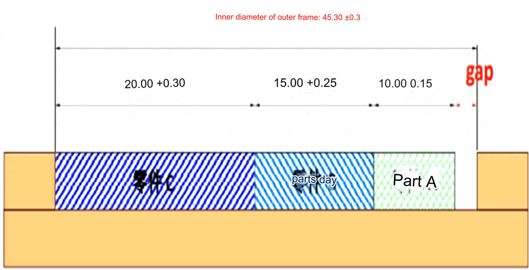
As shown in the figure, the rationality of the tolerance labeling is evaluated through calculation:
First calculate according to the upper deviation:
Maximum size of outer frame inner diameter: 45.6
Upper limit size of part A: 10.15
Limit size on part B: 15.25
Limit size on part C: 20.3
calculate:
45.6-10.15-15.25-20.3=-0.1
The interference will be 0.1mm if the parts reach the upper limit. This will cause the parts not to be assembled properly. It is clear that the drawing tolerance needs to be improved.
Then calculate the deviation by pressing:
Lower limit size of outer frame inner diameter: 45.0
Lower limit size of part A: 9.85
Lower limit size of part B: 14.75
Lower limit size of part C: 19.7
calculate:
45.0-9.85-14.75-19.7=0.7
If the parts are processed at a lower deviation then an assembly gap will be 0.7mm. It is not guaranteed that the parts will have the lower deviation when they are actually processed.
Then calculate based on zero deviation:
Basic inner diameter of outer frame: 45.3
Part A basic size: 10
Part B basic size: 15
Part C basic size: 20
calculate:
45.3-10-15-20=0.3
Note: Assuming the parts are in basic sizes, there will 0.3mm assembly gap. There is also no guarantee there won’t be any deviations in the sizes of the components during the actual processing.
Gaps that may appear after processing the drawings according to the standard tolerances of dimensions.
Maximum gap: 45.6-9.85-14.75-19.7= 1.3
Minimum gap: 45-10.15-15.25-20.3= -0.7
The diagram shows that even when parts are within tolerance, there may be a gap or interference of up to 0.7 mm. The assembly requirements could not be met in these extreme cases.
Combining the above analysis, assembly gaps for the three extremes are: -0.1, +0.7, and 0.3. Calculate the defect rate:
Calculate the number of defective parts to calculate the defect rate.
The defective rate is:
(x+y+z) / n x 100%
According to the conditions given in the question, the following system of equations can be listed:
x + y + z = n
x = n * ( – 0.1 / ( – 0.1 + 0.3 + 0.7) )
y = n * ( 0.7 / ( – 0.1 + 0.3 + 0.7) )
z = n * ( 0.3 / ( – 0.1 + 0.3 + 0.7) )
Put the above equations into the following formula to calculate the defective rate:
( – 0.1 * n / ( – 0.1 + 0.3 + 0.7) ) + ( 0.7 * n / ( – 0.1 + 0.3 + 0.7) ) + ( 0.3 * n / ( – 0.1 + 0.3 + 0.7) ) / n x 100%
The poor solution rate is 15.24%.
Combining the calculation of the tolerance with the risk of 15,24% defect rate, the product has to be adjusted for the assembly tolerance.
1. There is no closed-loop dimension chain, and the analysis and comparison are not based on the complete dimension chain.
2. Many conceptual errors exist. The editor has changed the “upper tolerance”, the “lower tolerance”, and the “standard tolerance”.
3. It is important to verify the algorithm for calculating yield rates.
The yield rate for parts processing is normal distributed. That is, the probability that cnc machined plastic parts are at their middle values is greatest. In this case, the most likely size of the part is its basic dimension.
Calculate the defective rate. This is the ratio between the number of defective components produced and the total number produced. How can we calculate the number parts using the gap value? It has nothing to with the final gap value required? If the dimensions are basic, then they can be classified and used in the calculation of defective rate.
Assembly dimension chain case 2
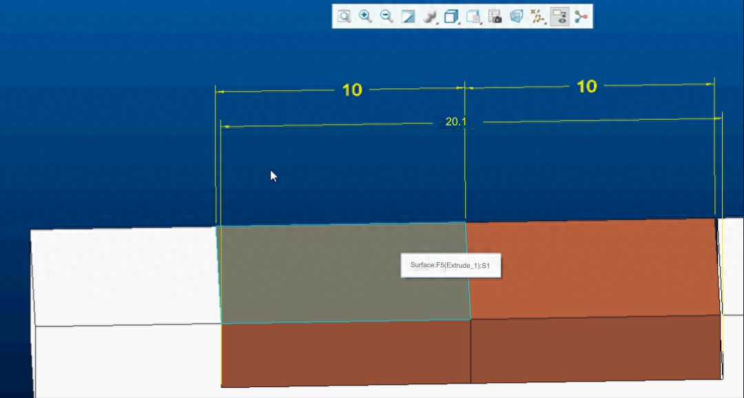
Make sure that the gap between the parts is greater than 0.1mm
The tolerance for part 1 is 10.00 + 0.00/-0.10
The tolerance for part 2 is 10.00 + 0.00/-0.10
The tolerance for assembly is 20.1+0.10/0.00.
As long as the assembly is within tolerance, it will not have any defects.
1. It is not clear what the final assembly gap is, and therefore it is difficult to judge if it qualifies.
2. Calculate the maximum and minimum clearance values based on project dimensions.
Maximum gap value : 20.2-9.9-9.9=0.4
Minimum gap value is 20-10-10=0
It is not possible to determine if it is qualified based on the gap between 0-0.4. The conclusion that there is “no phenomenon of poor assembly” is not true. .
Assembly dimension chain case 3
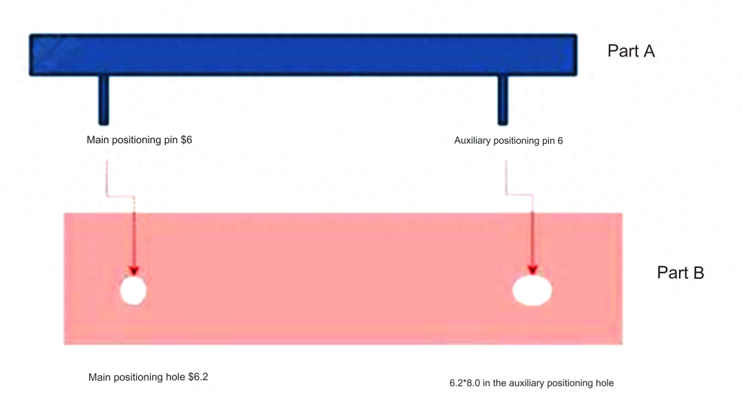
Between the shell position holes and posts, there are three sizes of chain.
The tolerance for the center distance between the two posts must be less than the male assembly tolerance in the first dimension chain.
The tolerance between the position posts and the holes must be smaller in the second dimension chain than the center distance of the two posts.
Third Dimension Chain: The tolerence of the position post must be less than that of the hole.
The tolerance for part A is 100+-0.15
Tolerance of part B: 99.8+0.15
The distance between the center pins of part A and part B is 70+-0.2
The distance between the center holes of part B is 70+-0.2
The diameter of part A’s positioning pin is 6+0.00/0.1
The diameter of part B’s positioning hole is 6.4+0.1/0.0
As shown in this figure, the tolerance mark will not affect an assembly if it meets the tolerance.
Positional tolerances are used to ensure that the final assembly requirements can be met. The pinholes and pins on part A and B as well as their positions are marked using position degrees.
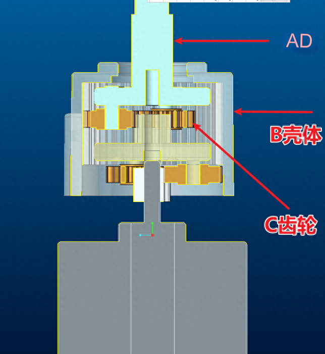
Assembly dimension chain case 4
As shown in figure, first confirm the tolerence of B housing. The tolerance for assembly of the A axis should be less than that of B housing and C gear. The transfer of B housing will not be affected if C gear is used.
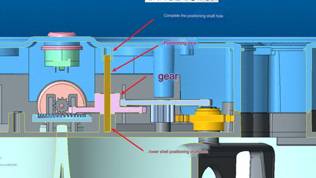
Assembly dimension chain case 5
The perpendicularity of the position axis to the lower shell is locked.
To ensure verticality, the lower shell and positioning shaft must be assembled with a tolerance greater than that of the upper shell.
To prevent the shaft from being pulled off its position once the upper shell has been assembled, the tolerance between the upper and lower shells should be larger than the tolerance of assembly of the positioning shaft.
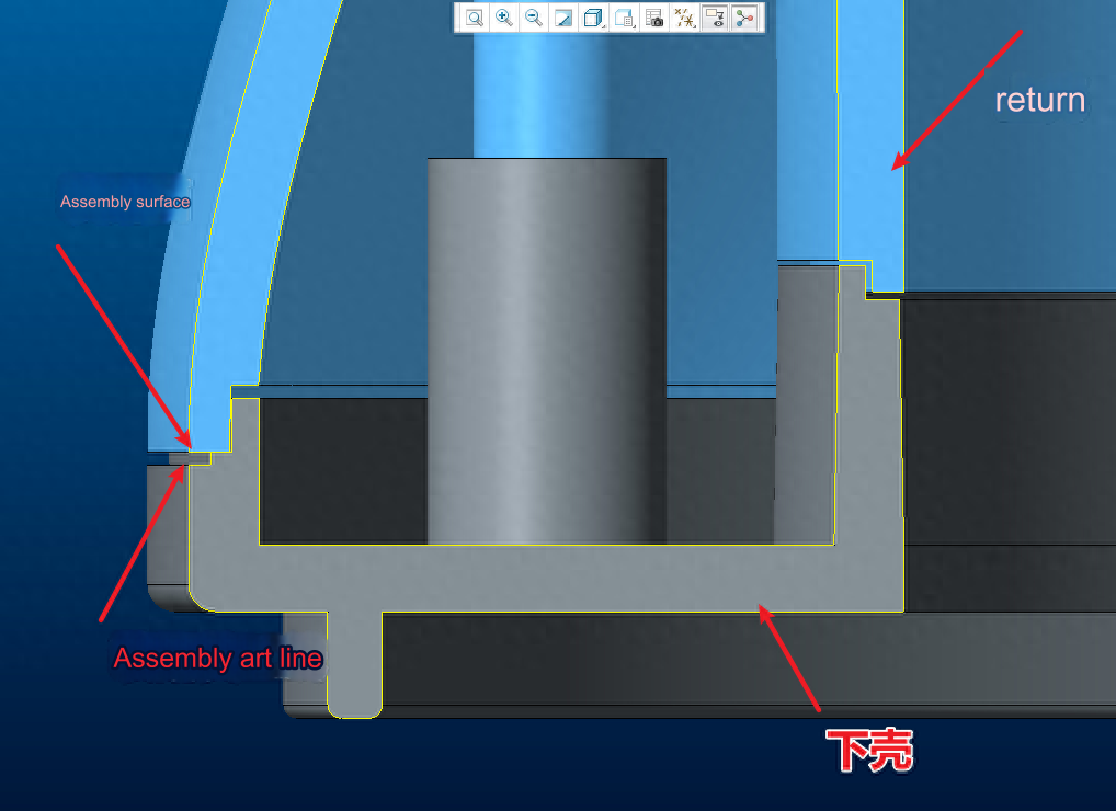
Assembly dimension chain case 6
To ensure consistency in the height of art line outside of the assembly, the tolerance for the concave joint of the lower housing must be smaller than that of the convex joint of the upper housing.
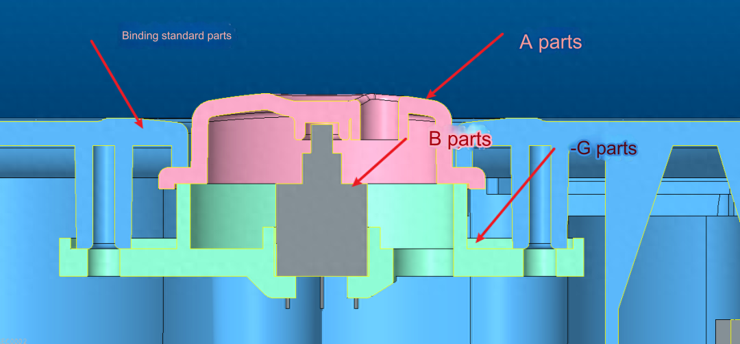
Assembly dimension chain case 7
To ensure there is no gap between the parts A and B, the tolerances of the part A plus the base assembly part must be larger than the part B and part C combined.
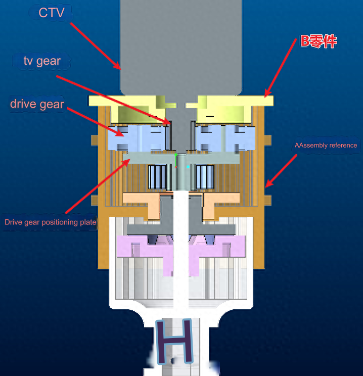
Assembly dimension chain case 8
First, as shown in the figure: first check the assembly tolerance A.
The tolerance between assembly datum A and motor C must be smaller than that between motor B and part B.
To ensure smooth rotation, the drive gear must rotate smoothly. The A assembly datum and drive gear tolerances should be less than each other.
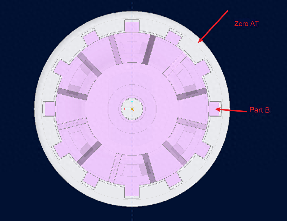
Assembly dimension chain case 9
To mark tolerances in the case of multipoint assembly, the small shaft and large holes principle is used. This will ensure that there is no assembly interference.
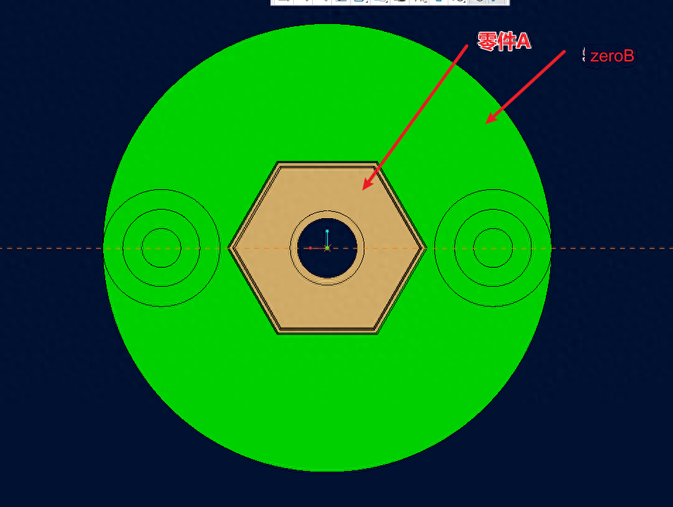
Assembly dimension chain case 10
Assembly interference will not occur because the tolerances of the hole are positive and the axis is negative.
With Anebon’s leading technology likewise as our spirit of innovation,mutual cooperation, benefits and development, we’re going to build a prosperous future together with your esteemed enterprise for OEM Manufacturer Custom High Precision aluminum parts, turning metal parts, cnc milling parts, And there are also a lot of overseas close friends who came for sight seeing, or entrust us to buy other stuff for them. You will be most welcome to come to China, to Anebon’s city and to Anebon’s manufacturing facility!
China Wholesale China machined components,cnc products, steel turned parts and stamping copper. Anebon has advanced production technology, and pursuit innovative in products. At the same time, the good service has enhanced the good reputation. Anebon believe that as long as you understand our product, you must be willing to become partners with us. Looking forward to your inquiry.
Post time: Oct-12-2023