
Do you know how many methods there are for precise tool setting on CNC lathes?
Touch Probe Method: - This method utilizes a probe that touches the tool to measure its position relative to the machine reference point. It gives accurate data on tool diameter and length.
Tool Pre-Setter: A tool-pre-setter fixture is used to measure the dimensions of the tool outside the machine. This method allows quick and accurate setup of the tool.
Tool Offset Method: – In this method, an operator measures the length and diameter of the tool using tools such as calipers and micrometers. The values are then entered into the machine’s controls system.
Laser Tool Measurement: Laser systems are used to set and measure tool dimensions. By projecting a beam of laser light onto the cutting edge of the tool, they provide accurate and quick tool data.
Image Recognition Method: Advanced computer systems can use image recognition technology to automatically calculate tool dimensions. They do this by taking images of the tool, analyzing its features and then calculating the measurements.
This is a very useful article. The article introduces first the principles and ideas behind the “trial-cutting tool-setting method” that is commonly used with CNC lathes. It then introduces four manual methods of trial cutting tool settings for CNC turning systems. To improve the accuracy of its tool settings, a program controlled automatic trial cutting method based on “automatic cutting – measuring – error compensating” was developed. Four accurate tool setting methods have also been summarized.
1. The principle and ideas behind the tool-setting method for CNC lathes
Understanding the CNC lathe tool-setting principles is important for operators who want to keep clear ideas about tool-setting, master tool-setting operations, and suggest new methods. Tool setting is determining the origin position of the workpiece coordinates system, which changes when programming the machine tool coordinates system. Tool setting involves obtaining the machine coordinates for the starting point of a reference tool program, and determining the tool offset relative to that tool.
The following conventions are used to demonstrate the concepts and ideas behind tool setting using the trial cutting method. Use the Hua Medieval Star Teaching Turning System (version number 5.30 of the application software); use the center of right end face on the workpiece for the program origin and set it up with the G92 command. Diameter programming, workpiece coordinates of the program start point H are (100,50); install four tools onto the tool holder. The tool No.1 is a 90deg rough turning tool and the No. Reference tool 2 is a 90deg outside circle fine turning tool. knife, No. No. The 4th knife is a triangular threaded knife with a 60deg angle (the examples in the article are all the same).
The “machine tool” coordinates are used for the tool setting. As shown in figure 1, the reference tool “manually test cuts the outer circle and the end face of workpiece and records the X-Z machine tool coordinates on the display. The machine tool coordinates for the program origin O are derived from the relationship between machine tool coordinates at point A and O: XO=XA – Phd, ZO=ZA. Using the workpiece coordinates for H in relation to point O (100,50), we can finally derive the machine tool coordinates for point H: XH=100 – Phd, ZH=ZA+50. This workpiece coordinate system is based upon the position of the tool tip on the reference tool.
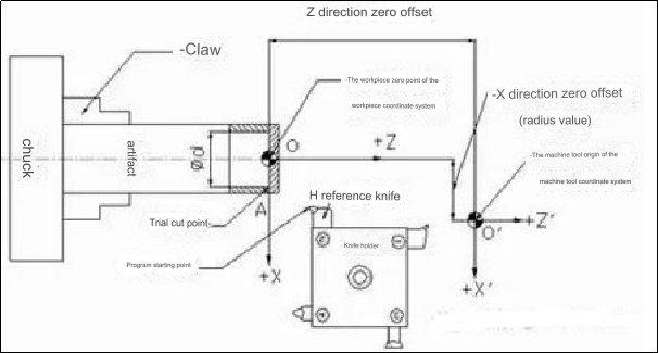
Figure 1 Schematic diagram for manual trial cutting and tool settings
In Figure 2, the offset between the point A and the tool tip B occurs due to the differences in extensions and positions in the X- and Z-direction of the tools clamped into the tool holder. The original coordinate system for the workpiece is no longer valid. Each tool will also wear at a different rate during use. Therefore, the tool offsets and wear values for each tool must be compensated.
To determine the tool offset, each tool must be aligned to a specific reference point (point A or B in Figure 1) on the workpiece. The CRT displays machine tool coordinates that are different from the tool offsets of the non-reference tools. Therefore, they are positioned at the same point. By using manual calculations or software calculations, the machine tool’s coordinates are subtracted from those of the reference tool. The tool offset is then calculated for each non-standard device.
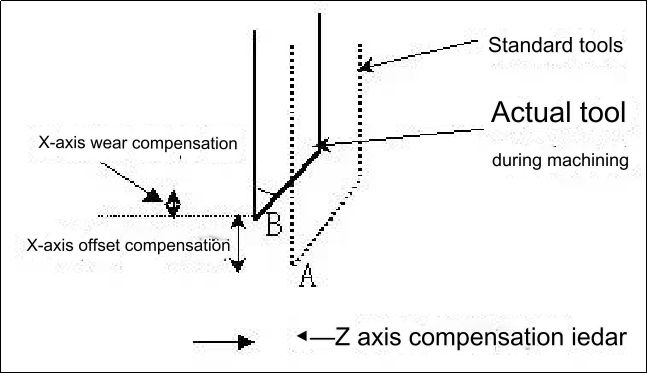
Figure 2 Compensation for tool offset and wear
The accuracy of manual trial cutting tool settings is limited. This is known as rough tooling. As shown in Figure 3, to achieve more accurate results within the machining allowances of the cnc auto part, a simple automated trial cutting program can be designed. The reference knife is continuously modified using the concept of “automatic cutting-measurement-error compensation”. The tool offset and program starting point of the non reference tool are used to make sure that the difference between the value of the processing instruction and the actual measured value meets the accuracy requirements. Precision tool setting is the tool setting that occurs at this stage.
It is common to correct the non-standard offsets after the initial correction. This is because ensuring the position of the reference tool’s starting point is accurate is a prerequisite for accurate tool offsets.
This basic tool setting process is achieved by combining these two stages: manually test cut the knife with the reference to obtain machine tool coordinates for the tool setting reference. – Calculate or automatically calculate the tool offsets of each non reference tool. – The reference knife is located at the approximate start of the program. – The reference knife repeatedly calls up the test cutting program. The tool holder will be moved in MDI or step mode to compensate for errors and correct the position of the starting point. After measuring the size the non base knife will repeatedly call the test-cutting program. The tool offset is corrected based on this offset. This means that the reference tool will be stationary at the exact start of the program.
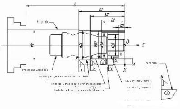
Figure 3 Schematic Diagram of Tool Setting for Multi-Knife Trial Cutting
Overview of rough knife setting techniques
To prepare for tool set-up, you can use any of the following methods: press the F2 key in the submenu of system MDI to access the tool offset table. Use the keys to move the highlight bar to the tool number position that corresponds to each tool and press the F5 button. Modify the X and Z offset values of tool offset numbers #0000 and #0001, then press the key F5.
1) Automatically set the tool offset method by selecting the reference tool.
The steps for setting the tool are shown in Figures 1 and 4.
The blue bar highlighted with the keys can be moved to align the tool offset #0002 for the No. 2 reference tool. Reference tool 2. To set the No.2, press the F5 key. The 2 tool will be set as the default tool.
2) Cut the outer circle with the reference tool and note the X machine-tool coordinates. After retracting the tool, stop the machine and measure the outer diameter of the shaft segment.
3) The reference blade returns to the point A recorded by the “jog+step” method. Input PhD and zero in the columns for the cutting diameter of the test and the cutting length of the test respectively.
4) Retract the standard tool and select the number of the nonstandard tool. Then, manually change the tool. The tool tip for each non-standard tools should be aligned visually with point A using the “jog+step” method. Adjust the corresponding offset after the tool is visually aligned. If you enter zero and PhD in the columns for the trial cutting length and diameter, the knife offsets of all non-reference knives will automatically be displayed in the X offset and Z offset column.
5) Once the reference tool has returned to point A, MDI will run “G91 G00/or” G01 X[100 PhD] Z50 to get to the program’s starting point.
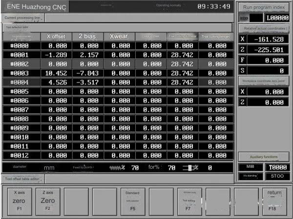
Figure 4 Schematic diagram of the reference tool automatically setting the tool offset for the standard tool
2. Set the coordinates of the reference tool to zero at the tool setting reference point and automatically display the tool offset method
As shown in Figure 1 and Figure 5, the tool setting steps are as follows:
1) Same as step (2) above.
2) The reference knife returns to the trial cutting point A through the “jog + step” method according to the recorded value.
3) In the interface shown in Figure 4, press the F1 key to “set the X-axis to zero” and press the F2 key to “set the Z-axis to zero”. Then the “relative actual coordinates” displayed by the CRT are (0, 0).
4) Manually change the non-reference tool so that its tool tip is visually aligned with point A. At this time, the value of “relative actual coordinates” displayed on the CRT is the tool offset of the tool relative to the reference tool. Use the ▲ and keys to move the blue Highlight the tool offset number of the non-reference tool, record it and input it into the corresponding position.
5) Same as the previous step (5).
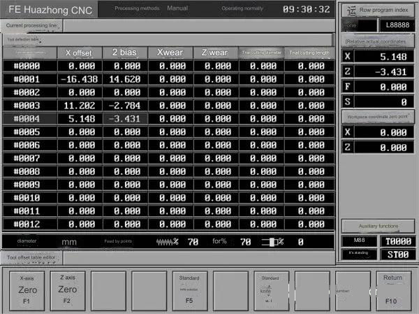
Figure 5 Schematic Diagram of the Tool Offset automatically displayed when the Reference Tool is set to zero in the tool setting reference points coordinates.
3. The knife offset method is calculated by manually calculating the trial cutting with multiple knives of the outer circular shaft segment.
As shown in figure 6, the system manually aligns knives 1, 2 and 4 and cuts out an axis. It then records the machine coordinates for the cutting ends of each knife. (Points F, D, and E in figure 6). Measure the diameter and length for each segment. Replace the No. 1 cutting knife. As shown in the image, cut a tool recess. Align the cutting blade with the right tip, record the coordinates for point B and measure L3 and PhD3 as per the figure. The incremental coordinate relationship between F, E and D points for each tool, and the O origin can be determined by comparing the data above.
It can then be seen that machine tool coordinates are (X2-PhD2+100 and Z2-L2+50) and machine tool coordinates for the program starting point corresponding to the reference tool. The method of calculation is shown in table 1. In the blanks, enter the calculated and recorded values. Note: The trial cutting distance is the distance between the coordinate zero point of the workpiece and the end point of the trial cut in the Z-direction. Positive and negative directions are determined by the coordinate axis.
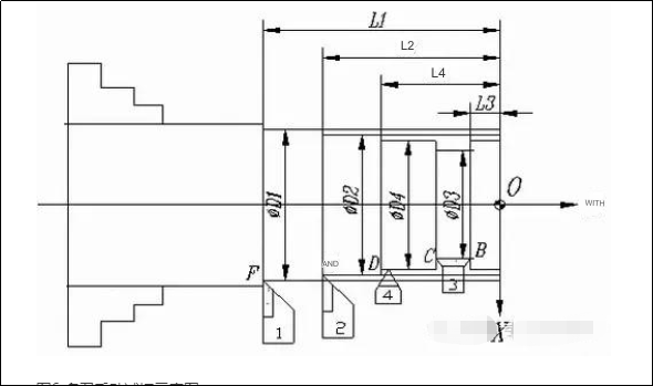
Figure 6 Schematic diagram of multi-knife manual trial cutting

Table 1 Calculation of tool offsets for non-standard Tools
This method allows for a simple test cutting procedure, as it eliminates the need to visually align the test cutting points. However, the knife offset must be calculated manually. You can calculate the tool offset quickly if you print the sheet with the formula and then fill in the blanks.
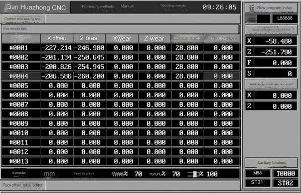
Figure 7 Schematic diagram for automatic tool setting on Century Star CNC system
Multi-tool automatic tool set method for 4th Century Star CNC system
All of the above mentioned methods for tool offset are relative methods. After professional staff have performed parameter setting and system testing, HNC-21T allows users to select the “absolute offset method” when setting up tools. In machining programming, the absolute tool offset is a little different than the relative tool off method. It is not necessary to use G92 or G54 for the workpiece coordinate systems, nor is it necessary to cancel tool compensation. See program O1005 for an example. As shown in Figure 6, after the system returns back to zero, let each knife try manually to cut a cylinder section.
Fill in the tool offset numbers for each knife after measuring the length and diameter. The trial cutting length is listed in the column for trial cutting diameter. The system software, using the method described in “Multiknife Cutting of External Shaft Segment – Manual Calculation for Knife Offset”, can calculate automatically the machine tool coordinates for each knife according to the origin of the program. This method of tool setting is the fastest, and it is particularly suitable for industrial production.
Summary of five accurate tool setting techniques
The principle of precise tool setting is “automatic measurement, automatic trial cutting and error compensation”. The error compensation can be divided into two categories: For the reference tool MDI operation, or step moving tool posts to compensate its program starting position; and for non-standard tool to compensate its tool offset or wear values. To avoid confusion, Table 2 has been designed to calculate and record values.

Table 2 Tool Setting Record Table for Trial Cutting Method (Unit: mm
1. Modify the offset method for each non-standard tool after the reference tool has corrected the starting point.
The steps for setting the tool are shown in Figure 3.
After rough tool calibration, the reference tool should be at the start of the program. Enter the offset of every non-standard tool in the appropriate position of the table.
Use the O1000 programme to process PhD2xL2 in order to make a trial cut.
Then, measure the diameter and the length of the segmented cutting shaft, compare them with the value in the command program, and determine the error.
Modify the start point of the program if the MDI error value or step movement is greater than the MDI error value.
5) Modify the O1000 command value dynamically based on the measured dimensions and save the program. Repeat steps (2) until the starting position of the reference tool is within the accuracy range. Note the machine-tool coordinates for the corrected program’s starting point. Set the coordinates at zero.
6) Dial the O1001(knife no. 1, No. O1002 (knife no. 3) for each trial cut, and measure the length Li (i=1, 2, 3) and diameter PhDi of each section.
7) Compensate for errors using the table 3 method.
Repeat steps 6 to 7 until the machining errors are within the range of accuracy and the reference tool is stopped at the start point of the programme and does not move.
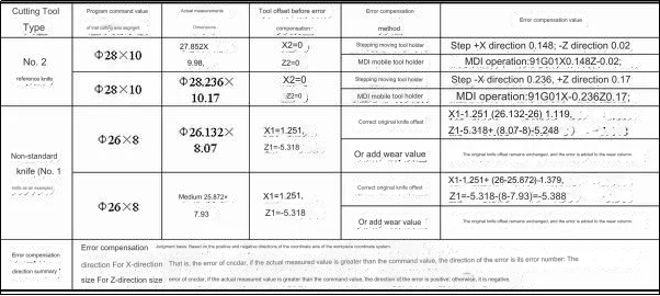
Table 3 Example of error compensation for automatic trial cutting of cylindrical shaft segments (unit: mm).
2. Modifying the starting position of each tool individually
This method’s tool-setting principle is that each tool adjusts its starting program point, thus indirectly aligning with the same origin position.
The steps for setting the tool are shown in Figure 3.
After rough tool calibration, the No. After rough tool calibration and recording the offsets, the No. 2 reference tool should be at the start of the program.
The steps 2) to (5) of the first accurate tool-setting method are identical.
Use the O1000 program to perform a trial cut. Measure the length Li and diameter PhDi of each section.
The step movement tool or MDI tool holder compensates for errors and adjusts each tool’s program starting point.
Repeat steps (6) until the starting position for each non-standard program tool is within the range of accuracy allowed.
The tool offset table can be accessed by entering the relative coordinates shown on the CRT into the X offset and Z offset column corresponding to the number of the tool offset. This method is convenient and simple. This method is simple and convenient.
3. Modify all offset methods for non-standard tools at the same moment after modifying the start position of the tool reference program.
The method is the same as that of the first accurate tool-setting method. The only difference between the two is that in step 7, the O1003 program is called, which calls three knives simultaneously (O1004 removes No. The O1003 program replaces the No. 2 section of tool processing. The remaining steps are identical.
6. Four knives can be repaired at once using this method
To find out the machining error, measure the diameter of each section, PhDi, and the length of each section, Li (i=2, 1, 4), using the relative tool-offset method. Use MDI or stepwise movement to the tool holder for the reference tool. Modify the program start point. For the non-standard tools, first correct the offset using the original offset. Then, enter the new offset. The machining error for the reference tool must also be entered in the wear column. Call the O1005 trial cutting program if the absolute tool offset is used to calibrate the tool. Then, compensate the machining errors of the tools in the wear columns of their respective tool offset numbers.
What impact does choosing the correct tool setting method for CNC lathes have on the quality of CNC machining parts?
Accuracy and precision:
The cutting tools will be properly aligned if the tool is set correctly. This directly impacts the accuracy and precision in machining operations. Incorrect tool setting can result in dimensional errors, poor surfaces finishes, and even scrap.
Consistency:
Consistent tool settings ensure uniformity of machining operations and consistent quality in multiple parts. It reduces variations in surface finish and dimensions, and helps to maintain tight tolerances.
Tool Life and Toolwear:
By ensuring that the tool is properly engaged with the workpiece, a correct tool setting can maximize tool life. Improper tool settings can result in excessive wear and breakage of tools, which will reduce tool life.
Productivity and Efficiency
Effective tool setting techniques can reduce machine setup time and increase uptime. It increases productivity by minimizing idle times and maximising cutting time. This allows for quicker tool changes and reduces overall machining times.
Operator Safety
The safety of the operator can be affected by choosing the correct tool setting method. Some methods like image recognition or laser tool measurement eliminate the need to handle tools manually, reducing the chance of injury.
Anebon’s goal is to understand excellent disfigurement from the manufacturing and supply the top support to domestic and abroad clients wholeheartedly for 2022 High quality Stainless Steel Aluminum High Precision Custom Made CNC Turning, Milling, cnc spare parts for Aerospace, In order to expand our international market, Anebon mainly supply our oversea customers Top quality performance mechanical parts, milled parts and cnc turning service.
China wholesale China Machinery Parts and CNC Machining Service, Anebon upholds the spirit of “innovation, harmony, team work and sharing, trails, pragmatic progress”. Give us a chance and we will be going to prove our capability. With your kind help, Anebon believe that we can create a bright future with you together.
Post time: Oct-19-2023