
Definition of Mechanical Knowledge by Anebon
Mechanical knowledge is the ability to understand and apply various mechanics concepts, principles and practices. Mechanical knowledge includes the understanding of machines, mechanisms and materials as well as tools and processes. This includes knowledge of mechanical principles, such as force and motion, energy and systems of gears and pulleys. Mechanical engineering knowledge includes design, maintenance and troubleshooting techniques, as well as mechanical engineering principles. Mechanical knowledge is important for many professions and industries that work with mechanical systems. These include engineering, manufacturing and construction.
1. What are the modes of failure of mechanical parts?
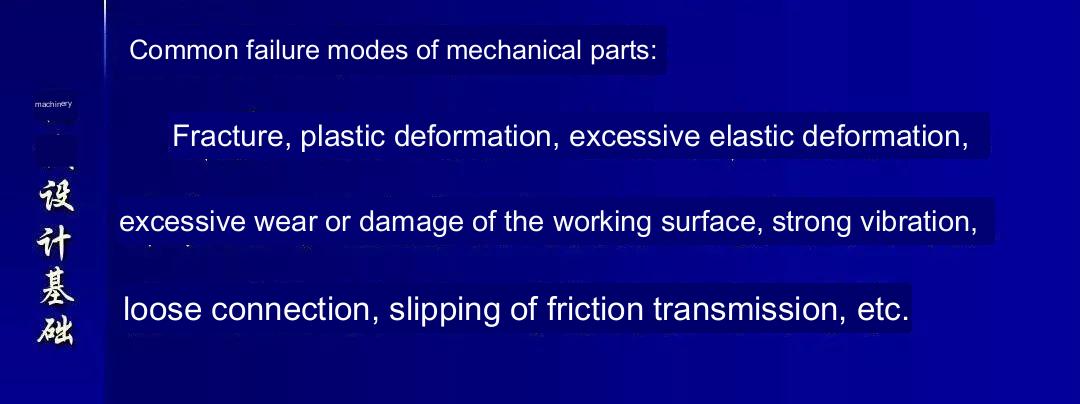
(1) Total breakage
(2) Excessive permanent distortion
(3) Part surface impairment
(4) Malfunction due to disruption of regular operating conditions
What is the rationale behind the frequent requirement of anti-unscrewing for threaded connections?
What is the core concept of anti-unscrewing?
What are the various methods available for preventing loosening?
Response:
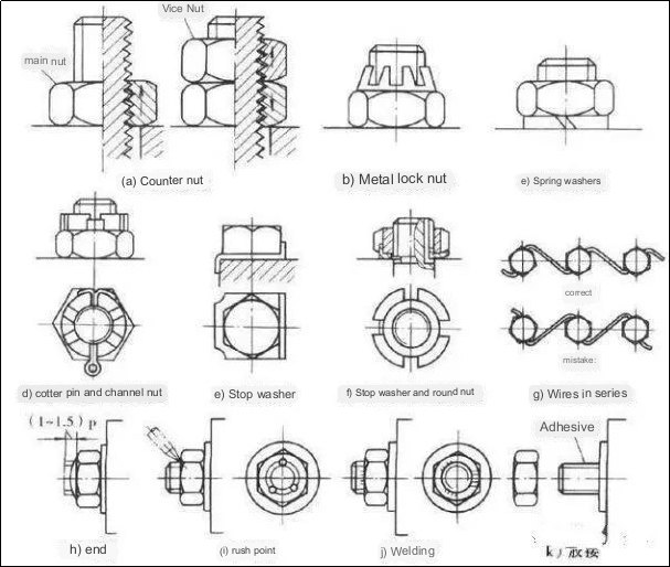
Generally, the threaded connection can fulfill the criteria of self-locking and will not spontaneously loosen. However, in situations involving vibrations, impact loads, or drastic temperature fluctuations, there is a likelihood of the connecting nut gradually loosening. The primary cause of thread loosening lies in the relative rotation between the thread pairs. Consequently, it is imperative to incorporate anti-loosening measures into the actual design.
The commonly employed methods comprise:
1. Friction-based anti-loosening — maintaining friction between the thread pairs to prevent loosening, such as utilizing spring washers and double nuts on the upper side;
2. Mechanical anti-loosening — utilizing obstructive machined components to guarantee anti-loosening, often employing slotted nuts and cotter pins, among others;
3. Disruption-based anti-loosening of thread pairs — modifying and altering the relationship between the thread pairs, such as through the application of an impact-based technique.
What is the objective of tightening in threaded connections?
Provide several approaches for controlling the applied force.
Answer:
The intention behind tightening in threaded connections is to allow bolts to generate pre-tightening force. This pre-tightening process strives to enhance the dependability and firmness of the connection to prevent any gaps or relative movement between the interconnected parts under loading conditions. Two effective techniques for controlling the tightening force are using a torque wrench or a constant torque wrench. Once the required torque is reached, it can be locked into place. Alternatively, the elongation of the bolt can be measured to regulate the pre-tightening force.
How does elastic sliding differ from skidding in belt drives?
In the design of a V-belt drive, why is there a limitation on the minimum diameter of the small pulley?
Answer:
Elastic sliding represents an inherent characteristic of belt drives that cannot be avoided. It occurs when there is a difference in tension and the belt material itself is an elastomer. On the other hand, skidding is a type of failure that arises due to overloading and should be prevented at all costs.
Specifically, skidding takes place on the small pulley. Increased external loads lead to a greater difference in tension between the two sides, which in turn results in an expansion of the area where elastic sliding occurs. Elastic sliding represents a quantitative change, whereas skidding signifies a qualitative change. Consequently, to prevent skidding, there is a limitation on the minimum diameter of the small pulley, as smaller pulley diameters result in smaller wrap angles and reduced contact areas, making slippage more likely to occur.
How does the sliding speed of the tooth surface relate to the allowable contact stress of gray cast iron and aluminum-iron bronze turbines?
Answer:
The allowable contact stress of gray cast iron and aluminum-iron bronze turbines is influenced by the sliding speed of the tooth surface due to the significant failure mode known as tooth surface adhesion. Adhesion is directly impacted by the sliding speed, thus affecting the permissible contact stress. On the other hand, the main failure mode of cast tin bronze turbines is tooth surface pits, which are caused by contact stress. Therefore, the allowable contact stress is unrelated to the sliding speed.
Enumerate the typical laws of motion, impact characteristics, and suitable scenarios for the cam mechanism follower.
Answer:
Motion laws for the cam mechanism follower include constant velocity motion, various deceleration motion laws, and simple harmonic motion (cosine acceleration motion law). The constant velocity motion law exhibits rigid impact and finds application in low-speed and light-load scenarios.
Deceleration motion laws, including constant acceleration, feature flexible impact and are suitable for medium to low-speed situations. Simple harmonic motion (cosine 4-chord acceleration motion law) offers soft impact when there is a pause interval, making it advantageous for medium to low-speed scenarios. In high-speed scenarios without rest intervals, there is no flexible impact, making it appropriate for those circumstances.
Summarize the fundamental principles governing tooth profile meshing.
Answer:
No matter where the tooth profiles make contact, the common normal line passing through the contact point must intersect a specific point on the center line. This condition ensures a consistent transmission ratio is maintained.
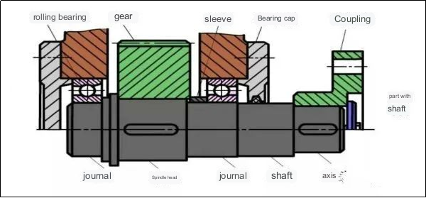
What are the various approaches to circumferentially fixing parts on a shaft? (provide more than four methods)
Answer:
Circumferential fixation possibilities include the utilization of a keyed connection, a splined connection, an interference fit connection, a set screw, a pin connection, and an expansion joint.
What are the primary types of axial fixing techniques for attaching parts to a shaft?
What are the distinguishing characteristics of each? (mention more than four)
Answer:
Axial fixing methods for attaching parts to a shaft encompass several key types, each with distinct characteristics. These include collar fixation, threaded fixation, hydraulic fixation, and flange fixation. Collar fixation involves the use of a collar or clamp that is tightened around the shaft to secure the part axially. Threaded fixation entails the use of threads on the shaft or part to firmly fasten them together. Hydraulic fixation employs hydraulic pressure to create a tight connection between the part and the shaft. Flange fixation involves the use of a flange that is bolted or welded to the cnc machining parts and the shaft, ensuring a secure axial attachment.
Why is it necessary to perform heat balance calculations for enclosed worm drives?
Answer:
Enclosed worm drives exhibit relative sliding and high levels of friction. Due to their limited heat dissipation capabilities and propensity for adhesion issues, conducting heat balance calculations becomes essential.
Which two strength calculation theories are employed in gear strength calculations?
What failures are they targeting?
If a gear transmission employs a closed soft tooth surface, what is its design criterion?
Answer:
Gear strength calculations involve determining the contact fatigue strength of the tooth surface and the bending fatigue strength of the tooth root. The contact fatigue strength is aimed at preventing fatigue pitting failures on the tooth surface, while the bending fatigue strength addresses fatigue fractures in the tooth root. A gear transmission employing a closed soft tooth surface follows the design criterion of considering the contact fatigue strength of the tooth surface and verifying the bending fatigue strength of the tooth root.
What are the respective functions of couplings and clutches?
How do they differ from each other?
Answer:
Both couplings and clutches serve the purpose of connecting two shafts to enable torque transmission and synchronized rotation. However, they differ in terms of their disengagement capabilities during operation. Couplings connect shafts that cannot be separated while in use; their disconnection is only possible by disassembling the turning parts after shutdown. On the other hand, clutches offer the ability to engage or disengage the two shafts at any given moment during machine operation.
Outline the essential prerequisites for oil film bearings to function properly.
Answer:
The two surfaces undergoing relative motion must establish a wedge-shaped gap; the sliding speed between the surfaces must guarantee lubricating oil entry from the larger port and exit from the smaller port; the lubricating oil must possess a specific viscosity, and an adequate oil supply is necessary.
Provide a brief explanation regarding the implications, distinguishing features, and typical applications of the bearing model 7310.
Answer:
Code interpretation: The code “7″ represents an angular contact ball bearing. The designation “(0)” refers to the standard width, with the “0″ being optional. The number “3″ signifies the medium series in terms of diameter. Finally, “10″ corresponds to an inner bearing diameter of 50mm.
Features and applications:
This bearing model can simultaneously endure radial and axial loads in a single direction. It offers a high limit speed and is typically used in pairs.
Within a transmission system incorporating gear transmission, belt transmission, and chain transmission, which type of transmission is typically placed at the highest speed level?
Conversely, which transmission component is arranged in the lowest gear position?
Explain the rationale behind this arrangement.
Answer:
Generally, the belt drive is positioned at the highest speed level, while the chain drive is placed in the lowest gear position. The belt drive boasts attributes like stable transmission, cushioning, and shock absorption, making it advantageous for the motor at higher speeds. On the other hand, chain drives tend to generate noise during operation and are better suited for low-speed scenarios, thus typically being allocated to the lower gear stage.
What causes the non-uniform velocity in chain transmission?
What are the primary factors influencing it?
Under what conditions can the instantaneous transmission ratio remain constant?
Answer:
1) The irregular speed in chain transmission is primarily caused by the polygonal effect inherent in the chain mechanism; 2) The key factors influencing it include chain speed, chain pitch, and sprocket tooth count; 3) When the number of teeth on both the larger and smaller sprockets are equal (i.e., z1=z2) and the center distance between them is an exact multiple of the pitch (p), the instantaneous transmission ratio remains constant at 1.
Why is the tooth width (b1) of the pinion slightly larger than the tooth width (b2) of the larger gear in cylindrical gear reduction?
When calculating strength, should the tooth width coefficient (ψd) be based on b1 or b2? Why?
Answer:
1) To prevent axial misalignment of the gears due to assembly errors, the meshing tooth width is reduced, leading to increased working load. Hence, the tooth width (b1) of the smaller gear should be slightly larger than b2 of the larger gear. The strength calculation should be based on the tooth width (b2) of the larger gear because it represents the actual contact width when a pair of cylindrical gears engage.
Why should the diameter of the small pulley (d1) be equal to or greater than the minimum diameter (dmin) and the wrap angle of the drive wheel (α1) be equal to or larger than 120° in deceleration belt drive?
Generally, the recommended belt speed is between 5 to 25 m/s.
What are the consequences if the belt speed exceeds this range?
Answer:
1) A smaller diameter of the small pulley leads to higher bending stress on the belt. To prevent excessive bending stress, the minimum diameter of the small pulley should be maintained.
2) The wrap angle (α1) of the drive wheel affects the maximum effective tension of the belt. Smaller α1 results in a lower maximum effective pulling force. To enhance the maximum effective pulling force and prevent slippage, a wrap angle of α1≥120° is generally recommended.
3) If the belt speed falls outside the range of 5 to 25 m/s, there can be consequences. A speed below the range might require a larger effective pulling force (Fe), leading to an increase in the number of belts (z) and a larger belt drive structure. Conversely, excessive belt speed would result in a higher centrifugal force (Fc), necessitating caution.
Pros and cons of helical rolling.
Answer:
Advantages
1) It exhibits minimal wear, and the adjustment technique can be applied to eliminate clearance and induce a certain level of pre-deformation, thereby enhancing rigidity and achieving high transmission accuracy.
2) Unlike self-locking systems, it is capable of converting linear motion into rotary motion.
Disadvantages
1) The structure is intricate and poses challenges in manufacturing.
2) Certain mechanisms may necessitate an additional self-locking mechanism to prevent reversal.
What is the fundamental principle for choosing keys?
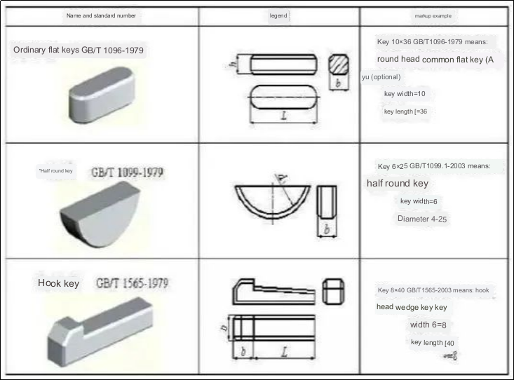
Answer:
When selecting keys, there are two key considerations: the type and the size. The type selection is dependent on factors such as the structural characteristics of the key connection, usage requirements, and working conditions.
On the other hand, the size selection should adhere to standard specifications and strength requirements. The size of the key consists of the cross-sectional dimensions (key width b * key height h) and the length L. The choice of cross-sectional dimensions b*h is determined by the shaft diameter d, while the key length L can generally be determined based on the length of the hub, meaning that the key length L should not exceed the length of the hub. Additionally, for guide flat keys, the hub length L’ is typically around (1.5-2) times the shaft diameter d, taking into consideration the length of the hub and the sliding distance.
Anebon relies on its strong technical capabilities and continuously develops advanced technologies to meet the requirements of CNC metal processing, 5 axis cnc milling, and automobile casting. We highly value all suggestions and feedback. Through good cooperation, we can achieve mutual development and improvement.
As an ODM manufacturer in China, Anebon specializes in customizing aluminum stamping parts and manufacturing machinery components. Currently, our products have been exported to over sixty countries and various regions around the world, including Southeast Asia, the Americas, Africa, Eastern Europe, Russia, and Canada. Anebon is committed to establishing extensive connections with potential customers in China and other parts of the globe.
Post time: Aug-16-2023