
Introduction:
In previous articles, our Anebon team has shared basic mechanical design knowledge with you. Today we will further learn the challenging concepts in mechanical design.
What are the main obstacles to mechanical design principles?
Complexity of design:
Mechanical designs are typically complex, and require engineers to combine diverse systems, components and functions.
For example, designing a gearbox that effectively transfers power without compromising other things like size and weight as well as noise is a challenge.
Material selection:
Selecting the right material for your design is essential, since they influence factors such as durability, strength, and cost.
For instance, selecting the suitable material for a high-stress component of an engine for aircraft isn’t easy due to the necessity to weigh down the weight while maintaining the capability to endure extreme temperatures.
Constraints:
Engineers have to work within limitations like time, budget and the available resources. This could limit the designs and necessitate the use of judicious tradeoffs.
For example, designing a efficient heating system that is cost-effective for a home and still complying with the energy efficiency requirements can pose issues.
Limitations in manufacturing
Designers must take into consideration their limitations in manufacturing methods and techniques when designing mechanical designs. In balancing the design intention with the capabilities of equipment and processes could be a problem.
For instance, designing a complex-shaped component that can only be produced through expensive machine or additive manufacturing techniques.
Functional requirements:
Fulfilling all requirements for the design, including safety, performance, or the reliability of a design, may be difficult.
For example, designing a brake system that provides exact stopping power, while also ensuring the safety of users can be a challenge.
Design optimization:
Finding the best design solution that balances many different goals, including weight, cost, or efficiency, isn’t easy.
For instance, optimizing the wings design of an aircraft to decrease drag and weight, without damaging structural integrity, requires sophisticated analyses and iterative design techniques.
Integration into the system:
Incorporating different components and subsystems into a unified design could be a huge issue.
For example, designing an automobile suspension system that regulates the movement of many components, while weighing factors such as comfort, stability and endurance can pose difficulties.
Design Iteration:
Design processes usually involve multiple revisions and iterations to refine and improve on the initial idea. Making design changes efficiently and effectively is a challenge both in terms of the time required and funds available.
For instance, optimizing the design of a consumer item by a series of iterations that improve the user’s ergonomics and aesthetics.
Considerations regarding the environment:
Integrating sustainability into the design and reducing the environmental impact of a building is becoming more essential. The balance between functional aspects and factors such as the ability to recycle, energy efficiency and emissions could be difficult. For example, designing a efficient engine that reduces greenhouse gas emissions, but not compromise performance.
Manufacturability design and assembly
The ability to ensure that a design will be manufactured and assembled within the time and cost constraints can be a problem.
For example, simplifying the assembly of a complicated product will decrease labor and manufacturing costs, while ensuring quality standards.
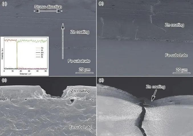
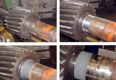
1. Failures are the result of mechanical components generally fractured, severe residual deformation, damage to the surface of components (corrosion wear, contact fatigue and wear) Failure due to wear and tear to the normal working environment.
2. The design components have to meet include requirements to ensure that they do not fail within the time-frame of their predetermined life (strength or stiffness, longevity) and structural process requirements economic requirements, low weight requirements, and reliability requirements.
3. Design criteria for components including strength and stiffness criteria, life requirements as well as vibration stability criteria and criteria for reliability.
4. Parts design methods: theoretical design, empirical design and model test design.
5. Commonly utilized for mechanical components are Metal materials, ceramic materials, polymer material as well as composite material.
6. The strength of the parts can be divided into static stress strength as well as variable stress strength.
7. Ratio of stress: = -1 is symmetrical stress in cyclic form; the r = 0 value is the cyclic stress that is pulsating.
8. It is believed that the BC stage is called strain fatigue (low cycle fatigue) CD refers to the infinite fatigue stage. The line segment following point D is the infinite life-failure level of the specimen. Point D is the permanent fatigue limit.
9. Strategies to improve the strength of parts that are fatigued reduce the effect of stress on elements (load relief grooves open rings) Choose materials that have high strength for fatigue and then specify the methods for heat treatment and strengthening techniques that increase the strength of fatigued the materials.
10. Slide friction: Dry friction boundaries frictions, fluid friction, and mixed friction.
11. The wear and tear process of components includes running-in stage, stable wear stage and the stage of severe wear We should try to reduce the time for running-in as well as extend the period of stable wear and defer the appearance of wear that is severe.
12. The classification of wear is Adhesive wear, abrasive wear and fatigue corrosion wear, erosion wear, and fretting wear.
13. Lubricants can be classified into four categories that are liquid, gas semi-solid, solid and liquid greases are classified into Calcium-based greases, Nano-based Grease aluminum-based grease, and lithium-based grease.
14. Normal connection threads feature an equilateral triangle form and excellent self-locking properties. rectangular transmission threads offer higher performance in transmission than other threads. Trapezoidal transmission threads are among the most popular transmission threads.
15. Connecting threads that are commonly used require self-locking, therefore single thread threads are commonly employed. Transmission threads need high efficiency for transmission and therefore triple-thread or double-thread threads are frequently used.
16. Regular bolt connections (the connected components include the holes through or are reamed) Double-headed stud connections screws, screw connections, as well as screws with set connections.
17. The goal of threaded connections pre-tightening is to improve the durability and strength of the connection, and to stop gaps or slippage between the two parts when loaded. The primary issue with tensioning connections that are loose is to stop the spiral pair from turning with respect to one another while loaded. (Frictional anti-loosening and mechanical to stop loosening, removing the link between the motion and the movement of the spiral couple)
18. Enhance the durability of threaded connections reduce the stress amplitude which influences the strength of fatigue bolts (reduce the stiffness of the bolt, or increase the stiffness of connecting custom cnc parts) and improve the uneven distribution of load over the threads. lessen the effect from stress accumulation, as well as implement a the most efficient manufacturing procedure.
19. Key connection types: flat connection (both sides work as a surface) semicircular key connection wedge key connection key connection with tangential angle.
20. Belt drive can be divided into two types: meshing type and friction type.
21. The moment of maximum stress for the belt is when the narrow part of it begins at the pulley. The tension changes four times in the course of one revolution on the belt.
22. Tensioning of the V-belt drive: Regular tensioning mechanism, auto tensioning device, and tensioning device that uses a the tensioning wheel.
23. Links in the roller chain is typically in an odd number (the quantity of tooth in the sprocket can be not a regular number). If the roller chain has unnatural numbers, then excessive links are employed.
24. The goal of tensioning the chain drive is to prevent meshing problems and chain vibration when the loose edges of the chain becomes too much, and to enhance the angle of meshing between the sprocket and the chain.
25. Failure modes of gears include: tooth breakage in gears and wear on the tooth surface (open gears) pitting of the tooth’s surface (closed gears) the tooth surface glue and the plastic’s deformation (ridges on the wheel driven grooves on the drive wheel).
26. Gears whose surface hardness is greater than 350HBS, or 38HRS are known as hard-faced or hard-faced or, if they’re not, soft-faced gears.
27. Enhancing manufacturing precision, decreasing the diameter of the gear to decrease the speed of rotation, could reduce dynamic load. In order to decrease dynamic burden, the gear may be cut. The purpose of turning the gear’s teeth into the drum is to increase the strength of the shape of the tooth tip. directional load distribution.
28. The bigger the lead angle of the diameter coefficient the greater the efficiency, and the less the self-locking ability.
29. The worm gear must be moved. After displacement the index circle as well as the worm’s pitch circle match however it is apparent that the line between the two worms has changed, and does not match the index circle of its worm gear.
30. Worm transmission failure modes such as pitting corrosion tooth root fracture the tooth’s surface glueing and excess wear; this is usually the case on the worm gears.
31. Power loss from closed worm drive meshing wear and wear on bearings as well as loss of oil splashes as the cnc milling components that are inserted into the pool of oil stir up the oil.
32. The worm drive should make thermal balance calculations based on the assumption that the energy generated per unit of time is the same as heat dissipation in the same period of time. Steps to take: Install heat sinks, and increase the area of heat dissipation and install fans on the ends of the shaft in order to increase the flow of air, and finally, install circulator cooling pipelines within the box.
33. Conditions that allow for the development of hydrodynamic lubrication: two surfaces that are sliding form a wedge-shaped gap that is convergent and the two surfaces that are separated by the oil film have to have a sufficient sliding rate and their motion must allow the oil lubricating to flow through the large opening into the smaller and lubrication must be of a certain viscosity, and the amount of oil available must be adequate.
34. The fundamental design of rolling bearings: outer ring, inner rings, hydraulic body and cage.
35. 3 roller bearings tapered five thrust bearings six deep groove ball bearings seven angular contact bearings N cylindrical roller bearings 01, 02and and 03 respectively. D=10mm, 12mm 15mm, 17,mm refers to 20mm is d=20mm, 12 is a reference to 60mm.
36. A basic life rating is the quantity of operating hours in where 10% of the bearings within a set of bearings are affected by pitting corrosion, but 90percent of them do not suffer from pitting corrosion damages is considered to be the longevity for the particular bearing.
37. Fundamental dynamic rating of load: the amount the bearing is capable of carrying in the event that the basic life for the unit is precisely 106 revolutions.
38. Method of bearing configuration: Each one of two fulcrums fixed in one direction. there is a fixed point in both directions, while the other fulcrum’s end is devoid of movement. Both sides are aided by a free motion.
39. Bearings are categorized in accordance with the load that is applied to the rotating shaft (bending time and torque) and spindle (bending moment) and transmission shaft (torque).
Anebon sticks into the basic principle of “Quality is definitely the life of the business, and status may be the soul of it” for big discount custom precision 5 Axis CNC Lathe CNC Machined Part, Anebon have confident that we could offer the high quality products and solutions at resonable price tag, superior after-sales support into the shoppers. And Anebon will build a vibrant long run.
Chinese Professional China CNC Part and Metal Machining Parts, Anebon rely on high-quality materials, perfect design, excellent customer service and the competitive price to win the trust of many customers at home and abroad. Up to 95% products are exported to overseas markets.
If you would like to know more or inquire about pricing, please contact info@anebon.com
Post time: Nov-24-2023