
The importance of the use of measuring tools in CNC machining
Precision and Accuracy:
Measuring tools enable machinists to achieve precise and accurate dimensions for the parts being manufactured. CNC machines operate based on precise instructions, and any discrepancies in measurements can result in defective or non-functional parts. Measuring tools such as calipers, micrometers, and gauges help verify and maintain the desired measurements, ensuring high precision in the machining process.
Quality Assurance:
Measuring tools are essential for quality control in CNC machining. By using measuring instruments, machinists can inspect the finished parts, compare them against the specified tolerances, and identify any deviations or defects. This allows for timely adjustments or corrections to be made, ensuring that the final products meet the required quality standards.
Tool Setup and Alignment:
Measuring tools are used to set up and align cutting tools, workpieces, and fixtures in CNC machines. Proper alignment is crucial to prevent errors, minimize tool wear, and maximize machining efficiency. Measuring instruments such as edge finders, dial indicators, and height gauges aid in accurately positioning and aligning components, ensuring optimal machining conditions.
Process Optimization:
Measuring tools also facilitate process optimization in CNC machining. By measuring the dimensions of machined parts at different stages, machinists can monitor and analyze the machining process. This data helps identify potential issues, such as tool wear, material deformation, or machine misalignment, allowing for adjustments to be made to optimize the manufacturing process and improve overall efficiency.
Consistency and Interchangeability:
Measuring tools contribute to achieving consistency and interchangeability of cnc machined parts. By accurately measuring and maintaining tight tolerances, machinists ensure that parts produced on different machines or at different times are interchangeable and function as intended. This is crucial for industries where precision and standardized components are essential, such as aerospace, automotive, and medical sectors.
Classification of measuring tools
Chapter 1 Steel Ruler, Internal and External Calipers and Feeler Gauge
1. Steel ruler
The steel ruler is the simplest length measuring tool, and its length has four specifications: 150, 300, 500 and 1000 mm. The picture below is a commonly used 150 mm steel ruler.
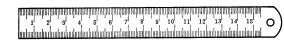
The steel ruler used to measure the length dimension of the part is not very accurate. This is because the distance between the marking lines of the steel ruler is 1mm, and the width of the marking line itself is 0.1-0.2mm, so the reading error is relatively large during measurement, and only millimeters can be read, that is, its minimum reading value is 1mm. Values smaller than 1mm can only be estimated.
If the diameter size (shaft diameter or hole diameter) of the cnc milling parts is directly measured with a steel ruler, the measurement accuracy is even worse. Its reason is: except that the reading error of steel ruler itself is bigger, also because steel ruler can’t just be placed on the correct position of part diameter. Therefore, the measurement of the diameter of the part can also be carried out by using a steel ruler and an internal and external caliper.
2. Internal and external calipers
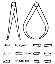
The picture below shows two common internal and external calipers. Internal and external calipers are the simplest comparison gages. The outer caliper is used to measure the outer diameter and flat surface, and the inner caliper is used to measure the inner diameter and groove. They themselves cannot directly read the measurement results, but read the measured length dimensions (diameter also belongs to the length dimension) on the steel ruler, or take off the required size on the steel ruler first, and then inspect the cnc turning parts Whether the diameter of the.
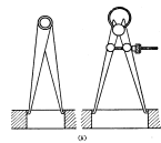
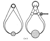
1. Adjustment of the opening of the caliper Check the shape of the caliper first. The shape of the caliper has a great influence on the measurement accuracy, and attention should be paid to frequently modifying the shape of the caliper. The figure below shows the caliper
The contrast between good and bad jaw shape.
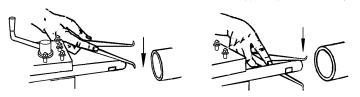
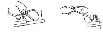
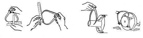
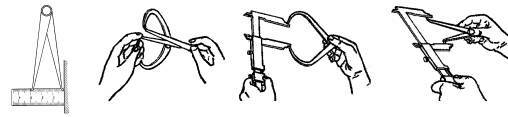
When adjusting the opening of the caliper, lightly tap the two sides of the caliper foot. First use both hands to adjust the caliper to an opening similar to the size of the workpiece, then tap the outside of the caliper to reduce the opening of the caliper, and tap the inside of the caliper to increase the opening of the caliper. As shown in Figure 1 below. However, the jaws cannot be struck directly, as shown in Figure 2 below. This can cause measurement errors due to the jaws of the caliper damaging the measuring face. Do not hit the caliper on the guide rail of the machine tool. As shown in Figure 3 below.
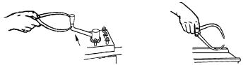
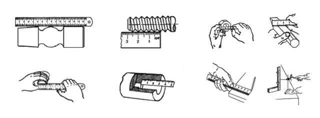
2. Use of the external caliper When the external caliper removes the size from the steel ruler, as shown in the figure below, the measuring surface of one pliers foot is against the end surface of the steel ruler, and the measuring surface of the other caliper foot is aligned with the required size marking line In the middle of the center, and the connecting line of the two measuring surfaces should be parallel to the steel ruler, and the line of sight of the person should be perpendicular to the steel ruler.
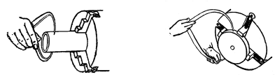
When measuring the outer diameter with an outer caliper that has been sized on a steel ruler, make the line of the two measuring surfaces perpendicular to the axis of the part. When the outer caliper slides over the outer circle of the part by its own weight, the feeling in our hands should be It is the point contact between the outer caliper and the outer circle of the part. At this time, the distance between the two measuring surfaces of the outer caliper is the outer diameter of the measured part.
Therefore, measuring the outer diameter with an external caliper is to compare the tightness of the contact between the external caliper and the outer circle of the part. As shown in the figure below, it is appropriate that the self-weight of the caliper can just slide down. For example, when the caliper slides over the outer circle, there is no contact feeling in our hands, which means that the outer caliper is larger than the outer diameter of the part. If the outer caliper cannot slide over the outer circle of the part due to its own weight, it means that the outer caliper is smaller than the outer diameter of the cnc machining metal parts.
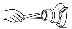
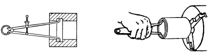
Never place the caliper on the workpiece obliquely for measurement, as there will be errors. As shown below. Due to the elasticity of the caliper, it is wrong to force the outer caliper over the outer circle, let alone push the caliper horizontally, as shown in the figure below. For a large-sized outer caliper, the measurement pressure of sliding through the outer circle of the part by its own weight is already too high. At this time, the caliper should be held for measurement, as shown in the figure below.
3. The use of inner calipers When measuring the inner diameter with inner calipers, the line of the measuring surfaces of the two pincers should be perpendicular to the axis of the inner hole, that is, the two measuring surfaces of the pincers should be the two ends of the diameter of the inner hole . Therefore, when measuring, the measuring surface of the lower pincer should be stopped on the hole wall as a fulcrum.
The upper caliper feet are gradually tested outward from the hole slightly inward, and swing along the circumferential direction of the hole wall. When the distance that can be swung along the circumferential direction of the hole wall is the smallest, it means that the two measuring surfaces of the inner caliper feet are in the middle position. The two ends of the bore diameter. Then slowly move the caliper from outside to inside to check the roundness tolerance of the hole.
Use the inside caliper that has been sized on a steel ruler or on the outside caliper to measure the inside diameter.
It is to compare the tightness of the inner caliper in the hole of the part. If the inner caliper has a large free swing in the hole, it means that the size of the caliper is smaller than the diameter of the hole; if the inner caliper cannot be put into the hole, or it is too tight to swing freely after being put into the hole, it means that the size of the inner caliper is smaller than the diameter of the hole.
If it is too large, if the inner caliper is put into the hole, there will be a free swing distance of 1 to 2 mm according to the above measurement method, and the hole diameter is exactly equal to the size of the inner caliper. Do not hold the caliper with your hands when measuring.
In this way, the hand feeling is gone, and it is difficult to compare the degree of tightness of the inner caliper in the hole of the part, and the caliper will be deformed to cause measurement errors.
4. Applicable scope of caliper Caliper is a simple measuring tool. Because of its simple structure, convenient manufacture, low price, convenient maintenance and use, it is widely used in the measurement and inspection of parts with low requirements, especially for forging Calipers are the most suitable measuring tools for the measurement and inspection of casting blank dimensions. Although the caliper is a simple measuring tool, as long as
If we master it well, we can also obtain higher measurement accuracy. For example, using external calipers to compare two
When the diameter of the root shaft is large, the difference between the shaft diameters is only 0.01mm.
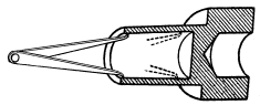
Experienced masters can also be distinguished. Another example is when using the inner caliper and the outer diameter micrometer to measure the inner hole size, experienced masters are completely sure to use this method to measure the high-precision inner hole. This inner diameter measurement method, called “inner snap micrometer”, is to use the inner caliper to read the accurate size on the outer diameter micrometer.
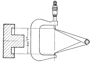
Then measure the inner diameter of the part; or adjust the degree of tightness in contact with the hole with the inner card in the hole, and then read the specific size on the outer diameter micrometer. This measurement method is not only a good way to measure the inner diameter when there is a lack of precise inner diameter measuring tools, but also, for the inner diameter of a certain part, as shown in Figure 1-9, because there is a shaft in its hole, it is necessary to use a precision measuring tool. If it is difficult to measure the inner diameter, the method of measuring the inner diameter with an inner caliper and an outer diameter micrometer can solve the problem.
3. Feeler gauge
Feeler gauge is also called thickness gauge or gap piece. It is mainly used to test the special fastening surface and fastening surface of the machine tool, the piston and the cylinder, the piston ring groove and the piston ring, the crosshead slide plate and the guide plate, the top of the intake and exhaust valve and the rocker arm, and the gap between the two joint surfaces of the gear. gap size. The feeler gauge is composed of many thin steel sheets of different thicknesses.
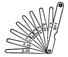
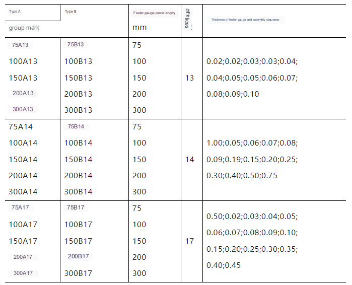
According to the group of feeler gauges, one by one feeler gauges are made, and each piece of feeler gauges has two parallel measuring planes, and has thickness marks for combined use. When measuring, according to the size of the joint surface gap, one or several pieces are stacked together and stuffed into the gap. For example, between 0.03mm and 0.04mm, the feeler gauge is also a limit gauge. See Table 1-1 for the specifications of the feeler gauge.
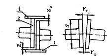
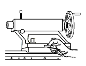
It is the positioning detection of the main engine and the shafting flange. Attach the ruler to the m feeler gauge on the plain line of the outer circle of the flange based on the shafting thrust shaft or the first intermediate shaft, and use the feeler gauge to measure the ruler and connect it. The gaps ZX and ZS of the outer circle of the crankshaft of the diesel engine or the output shaft of the reducer are measured at the four positions of the upper, lower, left and right of the outer circle of the flange in turn. The figure below is to test the gap (<0.04m) of the fastening surface of the tailstock of the machine tool.
When using the feeler gauge, the following points must be paid attention to:
1. Select the number of feeler gauge pieces according to the gap of the joint surface, but the fewer the number of pieces, the better;
2. Do not use too much force when measuring, so as not to bend and break the feeler gauge;
3. Workpieces with high temperature cannot be measured.
Anebon’s primary objective will be to offer you our shoppers a serious and responsible enterprise relationship, supplying personalized attention to all of them for New Fashion Design for OEM Shenzhen Precision Hardware Factory Custom Fabrication CNC milling process, precision casting, prototyping service. You may uncover the lowest price here. Also you are going to get good quality products and solutions and fantastic service here! You should not be reluctant to get hold of Anebon!
New Fashion Design for China CNC Machining Service and Custom CNC Machining Service, Anebon has numbers of foreign trade platforms, which are Alibaba,Globalsources,Global Market,Made-in-china. “XinGuangYang” HID brand products and solutions sell very well in Europe, America, Middle East and other regions more than 30 countries.
Post time: Jun-28-2023