
Why should we deburr processed products?
Safety:
Burrs may create sharp edges and protrusions, which can pose a risk to workers as well as end users.
Quality:
By removing burrs, you can improve the quality and appearance of your product.
Functionality:
Burrs can affect the performance of components and their interface with other parts.
Regulatory Compliance
Certain industries have strict regulations about burr tolerance levels in order to ensure product performance and safety.
Assembling and Handling
Deburred products make it easier to handle and assemble, which reduces the risk of damage.
Burrs are often generated during the metal cutting process. Burrs can reduce the accuracy of processing and the surface quality of a workpiece. They also affect the performance of a product and, in some cases, cause accidents. Deburring is usually used to solve the burr issue. Deburring is not a productive process. Deburring is a non-productive process. It increases costs, prolongs production cycles and can lead to scrapping the entire product.
The Anebon team has analyzed and described the factors that affect the formation of milling burrs. They have also discussed the methods and technologies available to reduce milling burrs and to control them, from the structural design phase to the manufacturing process.
1. End milling burrs: the main types
According to the system of classification for burrs based on cutting motion and tool cutting edge, the main burrs that are generated during end milling include burrs both on sides of the main surface, burrs along the side in the direction of cutting, burrs along the bottom in the direction cutting, and cut in and out feeds. There are five types of directional burrs.
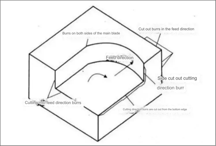
Figure 1 Burrs formed by end milling
In general, the size of burrs that are in the cutting direction at the bottom edge is larger and more difficult to remove. This paper focuses on the bottom edge burrs that are in the cutting directions. The size and shape can be classified into three different types of burrs that are found in the end milling cutting direction. Type I burrs can be difficult to remove and expensive, Type II burrs can be easily removed, and Type III burrs can be negative (as shown in figure 2).
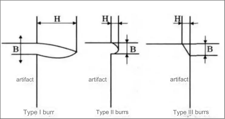
Figure 2 Burrs types in the milling direction.
2. The main factors that affect the formation of burrs on end milling machines
Burr formation is a complex process of material deformation. The formation of burrs is affected by a number of factors, including the material properties of the workpiece, its geometry, surface treatments, tool geometry and cutting path, wear on tools, cutting parameters, coolant usage, etc. The block diagram in Figure 3 shows the factors that affect end milling burrs. The shape and size end millings burrs depends on the cumulative effect of different influencing factors under specific milling conditions. However, different factors have different impacts on burr formation.
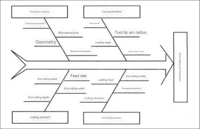
Figure 3: Cause and Effect Chart of Milling Burr Formation
1. Entry/exit of the tool
The burrs that are generated when the tool rotates away from the workpiece tend to be larger than those generated when it rotates inwards.
2. Remove the angle from the plane
The plane cut-out angles has a large influence on the formation burrs along the bottom edge. When the cutting edge rotates away from the terminal surface of a workpiece in the plane, passing through a particular point perpendicular the milling cutter’s axis at that point, the vector combination of toolspeed and feedspeed is equal to The angle between direction of end faces of he workpiece. The end face of the workpiece runs from the tool screw in point to the tool out point. In Figure 5, the range of Ps, the angle that is cut out of a plane is 0degPs=180deg.
Test results indicate that as cutting depth increases the burrs change from type I to type II. Usually, the minimum milling depth required to produce type II burrs (also known as limit cutting depth or dcr) is called a minimum milling depth. Figure 6 illustrates the impact of plane cutout angles and cutting depths on burr height during aluminum alloy machining.
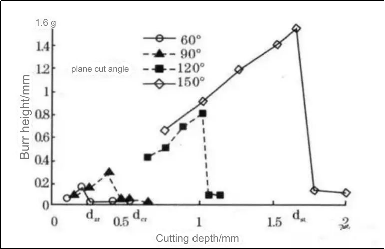
Figure 6 Plane cutting angle, burr form and cutting depth
The Figure 6 shows that, when the plane-cutting angle is greater that 120deg the type I burrs are larger and the depth at which they change to type II burrs increases. A small plane cutout angle will encourage the formation of type II burrs. The reason is that the lower the Ps value, the greater the stiffness of the surface at the terminal. This makes it less likely for burrs.
The feed speed and its direction will influence the speed and angle of plane cutting and the formation of burrs. The larger the feed rate and the offset of the edge at the exit, a, and the smaller the Ps, the more effective it is in suppressing the formation larger burrs.
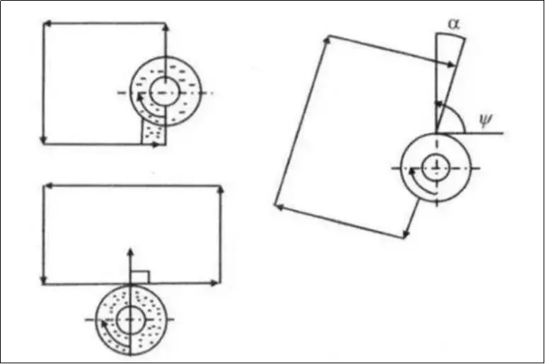
Figure 7 Effects of feed direction on burr production
3. Tool tip EOS exit sequence
The burr size is largely determined by the order in which the tool tip exits the end mill. In Figure 8, point A represents the minor cutting edge. Point C represents the main cutting edges. And point B represents the tip apex. The tool tip radius is ignored because it is assumed to be sharp. The chips will be hinged to the surface of the machined workpiece if edge A-B leaves the workpiece before edge B-C. As the milling process continues, the chips are pushed from the workpiece forming a large bottom edge cutting burr. If edge A-B leaves the workpiece before edge B-C, the chips will be hinged at the transition surface. They are then cut out from the workpiece in the direction of cutting.
The experiment shows:
① The tool tip exit sequence ABC/BAC/ACB/BCA/CAB/CBA that increases the burr size in sequence.
② The results of EOS are identical, except for the fact that the burr size produced in plastic materials under the same exit sequence is greater than that produced in brittle materials. The tool tip’s exit sequence is related not only to tool geometry but also factors like feed rate, milling deep, workpiece geometry, and cutting conditions. Burrs are formed by a combination multiple factors.
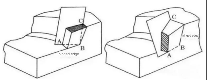
Figure 8 Tool tip burr formation and exit sequence
4. Influence of Other Factors
① Milling parameters (temperature, environment of cutting, etc.). The formation of burrs will also be affected by certain factors. Influence of major factors like feed speed, milling distance, etc. The plane cutting angle and tool tip exit sequence EOS theories are reflected in the theory of plane cutting angles. I won’t go into details here;
② The more plastic the material of the cnc turning parts, the easier it will be to form I type burrs. When end milling brittle material, large feed amounts or large plane cutting angles can lead to type III defects.
③ The increased stiffness of the surface can suppress the formation of burrs when the angle between the end surface and the machined plane exceeds a right-angle.
④ The use of milling liquid is beneficial for extending the life of tools, reducing wear and tear, lubricating the milling process and reducing burr sizes;
⑤ The wear of the tool has a significant impact on burr formation. The arc of the tip increases when the tool is worn to a certain degree. The burr size increases in the exiting direction of an instrument, and also in the cutting direction. Further study is needed to understand the mechanism. Dig deeper.
⑥ Other factors, such as the tool material, can also influence burr formation. Diamond tools suppress burrs better than other tools under the same conditions.
3. Controlling milling burrs formation is easy.
Many factors influence the formation of end-milling burrs. The milling process is only one factor that affects the formation of end milling burrs. Other factors include the geometry of the tool, the structure and size the workpiece, etc. In order to reduce the number of end milling burrs produced, it is necessary to control and reduce burr generation from multiple angles.
1. Reasonable structural design
Structure of the workpiece is an important factor in the formation of burrs. The shape and size after processing of burrs on the edges will also vary depending on the workpiece structure. When the material and surface treatment of the cnc parts are known, the geometry and edges play a major role in the formation of burrs.
2. Sequence of processing
The order in which the processing is performed can also have an impact on burr size and shape. Deburring is affected by the shape and size, as well as the deburring workload and costs. Deburring costs can be reduced by selecting the right processing sequence.
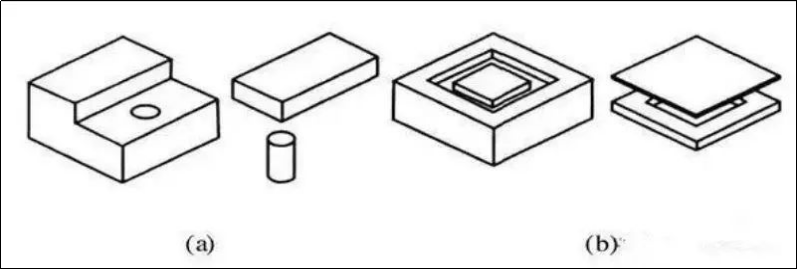
Figure 9 Selecting processing sequence control method
If the plane in Figure 10a is first drilled and then milled, then there will be large milling burrs around the hole. However, if it is first milled and then drilled, then only small drilling burrs are visible. In Figure 10b, a smaller burr is formed when the concave surface is first milled, followed by the milling of the upper surface.
3. Avoid Tool Exit
It is important to avoid tool withdrawal, as this is the primary cause of burrs forming in the cutting direction. The burrs that are produced when a milling tool is rotated away from the workpiece tend to be larger than those produced when it is screwed in. The milling cutter is to be avoided during processing as much as possible. Figure 4 shows that the burr created by using Figure 4b was smaller than the one produced by Figure 4.
4. Select the correct cutting path
The previous analysis shows that the size of the burr is smaller when the plane cut angle is lower than a certain number. Changes in milling width, rotation speed and feed speed can change the plane cutout angle. By selecting the appropriate tool path, it is possible to avoid creating I-type burrs (see Figure 11).
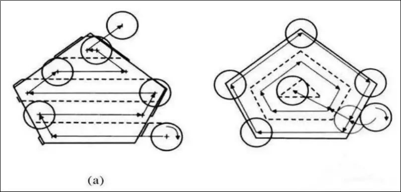
Figure 10: Controlling tool path
Figure 10a illustrates the traditional tool path. The shaded area of the figure shows the possible location where burrs can occur in the cutting direction. Figure 10b shows an improved tool path that can reduce the formation of burrs.
The tool path shown in Figure 11b may be slightly longer and take slightly more milling, but it doesn’t require any additional deburring. Figure 10a, on the other hand, requires much deburring (although there aren’t many burrs in this area, in reality, you have to remove all burrs from the edges). In summary, Figure 10b’s tool path is more effective at controlling burrs than Figure 10a’s.
5. Select appropriate milling parameters
The parameters of end milling (such as feed-per-tooth, end milling length, depth, and geometric angle) can have a significant impact on the formation of burrs. Burrs are affected by certain parameters.
Many factors influence the formation of end milling swarfs. The main factors include: tool entry/exit, plane cutting angles, tool tip sequences, milling parameters etc. The shape and size of the end milling burr are the result of many factors.
The article begins with the structural design of the workpiece, the machining process, the amount of milling and the tool selected. It then analyzes and discusses the factors that influence milling burrs and offers methods to control milling cutter paths, select appropriate processing sequences and improve structural design. The technologies, methods, and processes used to suppress or minimize milling burrs offer feasible technical solutions that can be applied in milling processing for active control of burr size and quality, cost reduction, and shorter production cycles.
Bear “Customer initial, High-quality first” in mind, Anebon perform closely with our clients and provide them with efficient and specialist expert services for Factory For CNC milling small parts, cnc machined aluminium parts and Die casting parts. Because Anebon always stay with this line more than 12 years. Anebon got most effective suppliers support on excellent and cost. And Anebon had weed out suppliers with poor high quality. Now several OEM factories cooperated with us too.
Factory For China Aluminum Section and Aluminum, Anebon can meet the various needs of customers at home and abroad. We welcome new and old customers to come to consult & negotiate with us. Your satisfaction is our motivation! Let Anebon work together to write a brilliant new chapter!
If you would like to know more or get a quote, please contact info@anebon.com
Post time: Dec-06-2023