
The fixture design is generally carried out according to the specific requirements of a certain process after the machining process of cnc machining parts and cnc turning parts is formulated. When formulating the process, the possibility of fixture realization should be fully considered, and when designing fixtures, if necessary, suggestions for modification of the process can also be proposed. The quality of the design of the fixture should be measured by whether it can stably guarantee the processing quality of the workpiece, high production efficiency, low cost, convenient chip removal, safe operation, labor saving, and easy manufacturing and maintenance.
1. Basic principles of fixture design
1. Satisfy the stability and reliability of workpiece positioning during use;
2. There is sufficient bearing or clamping strength to ensure the processing of the workpiece on the fixture;
3. Meet the simple and fast operation in the clamping process;
4. Vulnerable parts must have a structure that can be replaced quickly, and it is best not to use other tools when conditions are sufficient;
5. Satisfy the reliability of repeated positioning of the fixture during the adjustment or replacement process;
6. Avoid complex structure and high cost as much as possible;
7. Choose standard parts as component parts as much as possible;
8. Form the systematization and standardization of the company’s internal products.
2. Basic knowledge of fixture design
An excellent machine tool fixture must meet the following basic requirements:
1. To ensure the machining accuracy of the workpiece, the key to ensuring the machining accuracy is to correctly select the positioning datum, positioning method and positioning components. If necessary, it is necessary to analyze the positioning error. It is also necessary to pay attention to the impact of the structure of other parts in the fixture on the machining accuracy. To ensure that the fixture can meet the machining accuracy requirements of the workpiece.
2. To improve production efficiency, the complexity of special fixtures should be adapted to the production capacity, and various fast and efficient clamping mechanisms should be used as much as possible to ensure convenient operation, shorten auxiliary time, and improve production efficiency.
3. The structure of the special fixture with good process performance should be simple and reasonable, which is convenient for manufacturing, assembly, adjustment, inspection and maintenance.
4. The tooling fixture with good performance should have sufficient strength and rigidity, and the operation should be simple, labor-saving, safe and reliable. Under the premise that objective conditions permit and are economical and applicable, mechanical clamping devices such as pneumatic and hydraulic pressure should be used as much as possible to reduce the labor intensity of the operator. The fixture should also facilitate chip removal. If necessary, a chip removal structure can be set to prevent the chip from damaging the positioning of the workpiece and damaging the tool, and prevent the accumulation of chips from bringing a lot of heat and causing deformation of the process system.
5. The special fixture with good economy should use standard components and standard structure as much as possible, and strive to have a simple structure and easy manufacture to reduce the manufacturing cost of the fixture. Therefore, the necessary technical and economic analysis of the fixture scheme should be carried out according to the order and production capacity during the design, so as to improve the economic benefits of the fixture in production.
3. Overview of the standardization of tooling and fixture design
1. Basic methods and steps of fixture design
Preparations before design The original materials for fixture design include the following:
a) Technical information such as design notice, part finished product drawing, blank drawing and process route, understand the processing technical requirements of each process, positioning and clamping scheme, processing content of the previous process, blank condition, machine tools and tools used in processing , Inspection measuring tools, machining allowance and cutting amount, etc.;
b) Understand the production batch and the need for fixtures;
c) Understand the main technical parameters, performance, specifications, precision and contact dimensions of the structure connected with the fixture, etc. of the machine tool used;
d) The inventory of standard materials for fixtures.
2. Problems considered in the design of fixtures
Fixture design generally has a single structure, giving people the feeling that the structure is not very complicated, especially now that the popularity of hydraulic fixtures greatly simplifies the original mechanical structure, but if no detailed consideration is given during the design process, unnecessary troubles will inevitably occur:
a) The blank allowance of the workpiece to be processed. The size of the blank is too large, resulting in interference. Therefore, it is necessary to prepare the rough drawing before designing. Leave enough space.
b) Chip removal smoothness of the fixture. Due to the limited processing space of the machine tool during design, the fixture is often designed in a relatively compact space. At this time, it is often ignored that the iron filings generated during the machining process accumulate in the dead corner of the fixture, including the poor flow of cutting fluid, which will cause future problems. Processing brings a lot of trouble. Therefore, at the beginning of the actual process, the problems that arise during the processing should be considered. After all, the fixture is based on improving efficiency and facilitating operation.
c) The overall openness of the fixture. Ignoring the openness makes it difficult for the operator to install the card, which is time-consuming and laborious, and the design is taboo.
d) Basic theoretical principles of fixture design. Each set of fixtures has to go through countless times of clamping and loosening actions, so it may meet the user’s requirements at the beginning, but the added fixtures should have its accuracy retention, so don’t design something that goes against the principle. Even if you can do it now by luck, it won’t last long. A good design should stand the test of time.
e) Replaceability of positioning elements. The positioning element is severely worn, so quick and easy replacement should be considered. It is best not to design it as a larger part.
The accumulation of fixture design experience is very important. Sometimes design is one thing, but it is another thing in practical application, so good design is a process of continuous accumulation and summary.
Commonly used fixtures are mainly divided into the following types according to their functions:
01 clamping mold
02 Drilling and milling tooling
03 CNC, instrument chuck
04 Gas test, water test tooling
05 Trimming and punching tooling
06 welding tooling
07 Polishing fixture
08 Assembly tooling
09 pad printing, laser engraving tooling
01 clamping mold
Definition: A tool for positioning and clamping with product shape
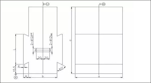
Design Points:
1. This type of clamping mold is mainly used for vise, and its length can be cut according to needs;
2. Other auxiliary positioning devices can be designed on the clamping mold, and the clamping mold is generally connected by welding;
3. The above picture is a simplified picture, and the size of the mold cavity structure is determined by the specific situation;
4. Tightly match the positioning pin with a diameter of 12mm at the appropriate position on the movable mold, and the positioning hole at the corresponding position of the fixed mold slides to fit the positioning pin;
5. The assembly cavity needs to be offset and enlarged by 0.1mm on the basis of the outline surface of the rough drawing without shrinkage during design.
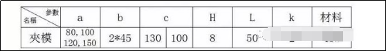
02 Drilling and milling tooling
Design Points:
1. If necessary, some auxiliary positioning devices can be designed on the fixed core and its fixed plate;
2. The above picture is a simplified structure diagram, and the actual situation needs to be designed according to the product structure;
3. The cylinder depends on the size of the product and the stress during processing, and SDA50X50 is commonly used;
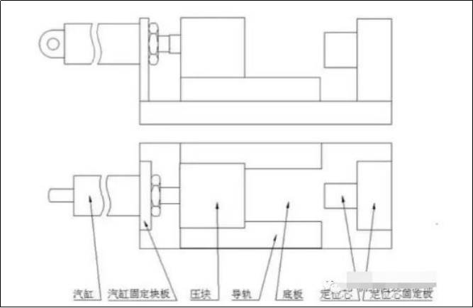
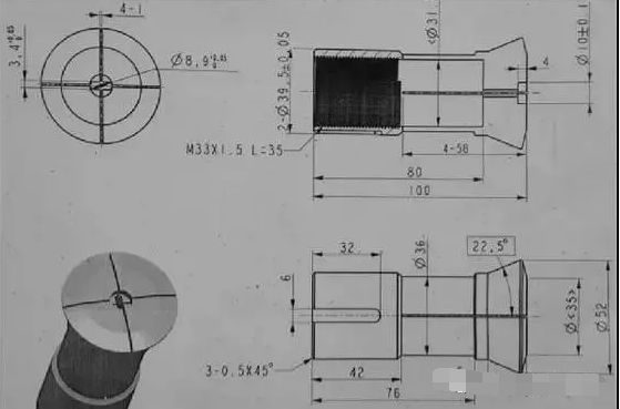
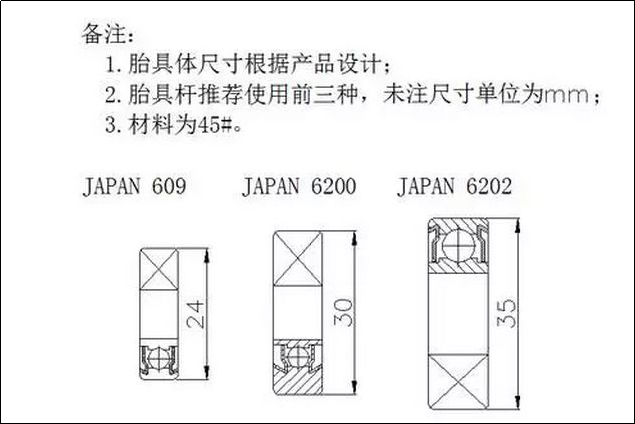
03 CNC, instrument chuck
A CNC Chuck
Inner collet
Design Points:
1. The size not marked in the above figure is determined according to the inner hole size structure of the actual product;
2. The outer circle that is in contact with the inner hole of the product needs to leave a margin of 0.5mm on one side during production, and finally install it on the CNC machine tool and finish turning it to size to prevent deformation and eccentricity caused by the quenching process;
3. The material of the assembly part is recommended to use spring steel, and the tie rod part is 45#;
4. The thread M20 of the tie rod is a common thread, which can be adjusted according to the actual situation
Instrument Inner Beam Chuck
Design Points:
1. The above picture is a reference illustration, and the assembly size and structure are determined according to the actual product’s external dimension and structure;
2. The material is 45#, quenched.
Instrument outer beam chuck
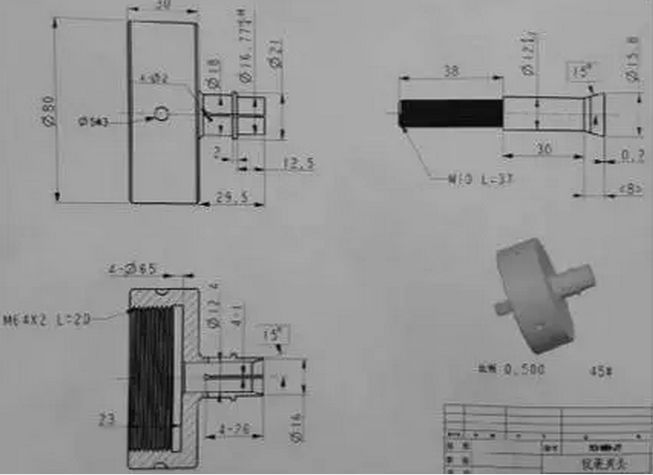
Design Points:
1. The above picture is a reference illustration, and the actual size depends on the size and structure of the inner hole of the product;
2. The outer circle that is in contact with the inner hole of the product needs to leave a margin of 0.5mm on one side during production, and finally install it on the instrument lathe and finish turning it to size to prevent deformation and eccentricity caused by the quenching process;
3. The material is 45#, quenched.
04 Gas test tooling
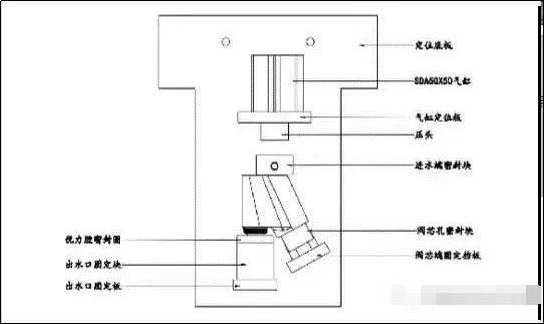
Design Points:
1. The above picture is a reference picture of the gas test tool. The specific structure needs to be designed according to the actual structure of the product. The idea is to seal the product in the simplest possible way, and let the part that needs to be tested be filled with gas to confirm its tightness;
2. The size of the cylinder can be adjusted according to the actual size of the product, and it is also necessary to consider whether the stroke of the cylinder can meet the convenience of picking and placing the product;
3. The sealing surface that is in contact with the product is generally made of excellent rubber, NBR rubber ring and other materials with good compression. At the same time, it should be noted that if there is a positioning block that is in contact with the appearance of the product, try to use white plastic plastic blocks and use them during use. The middle cover is covered with cotton cloth to prevent the appearance of the product from being damaged;
4. The positioning direction of the product should be considered in the design, so as to prevent the leakage of gas from being trapped inside the product cavity and cause false detection.
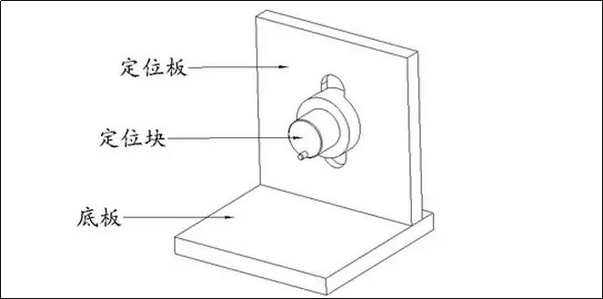
05 punching tooling
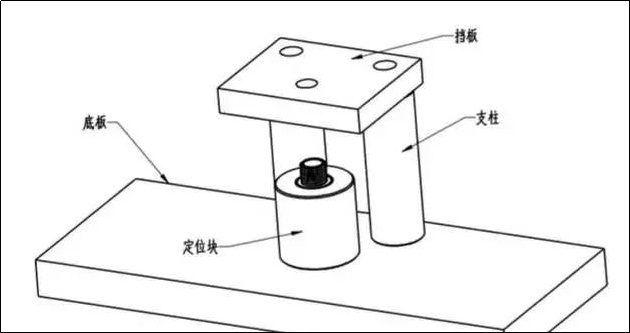
Design points: The picture above shows the common structure of punching tooling. The function of the bottom plate is to facilitate fixing on the workbench of the punching machine; the function of the positioning block is to fix the product, the specific structure is designed according to the actual situation of the product, and the center point is around to facilitate and safely pick and place the product; the function of the baffle is to facilitate the product to be separated from the punching knife ; The pillar acts as a fixed baffle. The assembly positions and dimensions of the above-mentioned parts can be designed according to the actual situation of the product.
06 welding tooling
The welding tooling is mainly used to fix the position of each component in the welding assembly and control the relative size of each component in the welding assembly. Its structure is mainly a positioning block, which needs to be designed according to the actual structure of aluminum machining parts and brass machining parts. It is worth noting that when the product is placed on the welding tool, it is not allowed to create a sealed space between the tools to prevent the excessive pressure of the sealed space during the welding heating process from affecting the size of the parts after welding.
07 Polishing fixture
08 Assembly tooling
Assembly tooling is mainly used as a device for auxiliary positioning during the assembly process of components. Its design idea is that the product can be easily taken and placed according to the assembly structure of the components, the appearance surface of the product cannot be damaged during the assembly process, and the product can be covered with cotton cloth to protect the product during use. In the selection of materials, try to use non-metallic materials such as white glue.
09 pad printing, laser engraving tooling
Design points: Design the positioning structure of the tooling according to the lettering requirements of the actual situation of the product. Attention should be paid to the convenience of taking and placing the product and the protection of the product appearance. The positioning block and the auxiliary positioning device in contact with the product should be made of non-metallic materials such as white glue. .
Post time: Dec-26-2022